SRP981 Pneumatic Positioner
Description
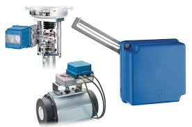
The SRP981 Positioner is for operation of pneumatic valve actuators with pneumatic control signals. It is used to reduce the adverse effects of valve friction, for higher thrust and shorter positioning time.
FEATURES
- Independent adjustment of stroke range and zero
- Adjustable amplification and damping
- Split range up to 4-fold possible
- Supply pressure up to 6 bar (90 psig)
- Low vibration effect in all directions
- Mounting according to IEC 534, part 6 (NAMUR)
- Rotation adapter for angles up to 120 °
- Ambient temperature –40 to 80 °C (–40 to 176 °F)
- Travel 8 to 100 mm (0.3 to 4 in)
- Angular range 30 ° to 120 °
- Modular system of additional equipment
- Electrical limit switches
- Electrical position transmitter
- Booster
- Connection manifold
- Protection class IP54 (IP 65 on request)
- Certificate No. 90/20226(E2) Lloyd’s Register of Shipping for use on vessels
- Explosion Protection
- pneumatic basic device: ATEX II 2 G c IIC T6 constructive design
- electrical additional built-in equipment: ATEX II 2 G Ex ib/ia IIB/IIC T4/T6 CU TR explosion protection
SPECIAL VERSION OF SRP981
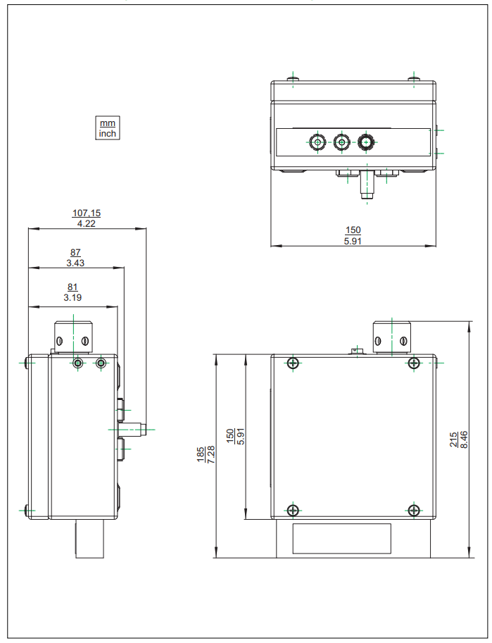
SRP981 in Stainless Steel housing
| Casing | Stainless Steel 1.4404 / 316L, 1.25 mm thick |
| Ingress Protection | IP65; IP66 under working conditions (supplied by air supply) |
| Impact Resistance | > 7 Joule acc. to EN 50014 |
| Seals | VMQ (Silicone) |
For dimensional drawings see further down this page
Version for mounting to linear actuators, single acting can be ordered under special version ECEP EP 0301, together with Mounting kit EBZG. Other versions for double acting or mounting to rotary actuators on request.
TECHNICAL DATA
Input
| Signal range | 0.2 to 1 bar (3 to 15 psig) or split range down to ∆w 0.2 bar (3 psi) |
| Stroke range | 8 to 100 mm (0.3 to 4 in) |
| Angular range linear | 30 ° to 120 ° |
| equal percentage | 90 °; from 70 ° linear |
Output
| Output to actuator | 0 to 100% supply air pressure |
Supply
| Supply air pressure | 1.4 to 6 bar (20 to 90 psig) |
| Air supply - Solid particle size and density - Oil rate - Pressure dew point 10 K under ambient temperature |
according to ISO 8573-1 |
| For air supply, we recommend the FRS02 filter regulator. | |
Ambient conditions
| Ambient temperature | –40 to 80 °C (–40 to 176 °F) |
| Relative humidity | up to 100% |
Operating condiutions
Operating conditions as per IEC 654-1: The device can be operated at a class D2 location
Transport and Storage
| Temperature | –50 to 80 °C (–58 to 176 °F) |
| Protection Class | IP 54 (IP 65 on request) |
Response characteristic
| Amplification | adjustable |
| Sensitivity | < 0.1 % F.S. |
| Non-linearity (terminal based adjustment) | < 0.1 % F.S. |
| Hysteresis | < 0.3 % F.S. |
| Supply air dependency | < 0.2 % / 0.1 bar (1.5 psi) |
| Temperature effect | < 0.3 % / 10 K |
Air consumption
| supply air pressure | air consumption |
| Single acting | |
| 1.4 bar (20 psig) | 200 ln /h ( 7.1 scfh) |
| 3.0 bar (45 psig) | 400 ln /h (12.4 scfh) |
| 6.0 bar (90 psig) | 600 ln /h (21.2 scfh) |
| Double acting | |
| 1.4 bar (20 psig) | 350 ln /h (10.6 scfh) |
| 3.0 bar (45 psig) | 550 ln /h (17.7 scfh) |
| 6.0 bar (90 psig) | 750 ln /h (33.5 scfh) |
Air output
| Load effect | –3 % for delivery flow 2 350 ln /h (83 scfh) |
| +3 % for exhausted flow 1 900 ln /h (67 scfh) |
Capacity at max. deviation
|
Supply air |
1.4 (20) | 2 (30) | 4 (60) | 6 (90) |
| without booster ln/h (scfh) | 2700 (95) | 3500 (124) | 5500 (194) | 7500 (265) |
| with booster code VKXG -FN ,-GN ln/h (scfh) | 18000 (636) | 24000 (847) | 40000 (1412) | 55000 (1942) |
| with booster code VKXG -HN ln/h (scfh) | 36000 (1271) | 48000 (1695) | 80000 (2825) | 110000 (3884) |
Data measured according to VDI/VDE 2177
Material
| Base Plate | Aluminum (Alloy No. 230) finished with DD-varnish blue |
| Cover | impact resistant polyester blue |
| All moving parts of feedback system | 1.4305 / 1.4571 |
| Mounting bracket | 1.4301 |
Weight
| Single acting | |
| without gauges | approx. 0.7 kg (1.5 lbs) |
| with gauges | approx. 0.8 kg (1.8 lbs) |
| Double acting | approx. 0.9 kg (2.0 lbs) |
| Attachment kit | |
| for diaphragm actuators | approx. 0.3 kg (0.6 lbs) |
| for rotary actuators | approx. 0.5 kg (1.1 lbs) |
Connection
| Pneumatic | Female threads G 1/8 acc. to ISO 228 |
Mounting
| Type of mounting | for attaching to diaphragm actuators acc. IEC 534-6 (NAMUR |
| for attaching to rotary actuators | |
| Mounting orientation | any |
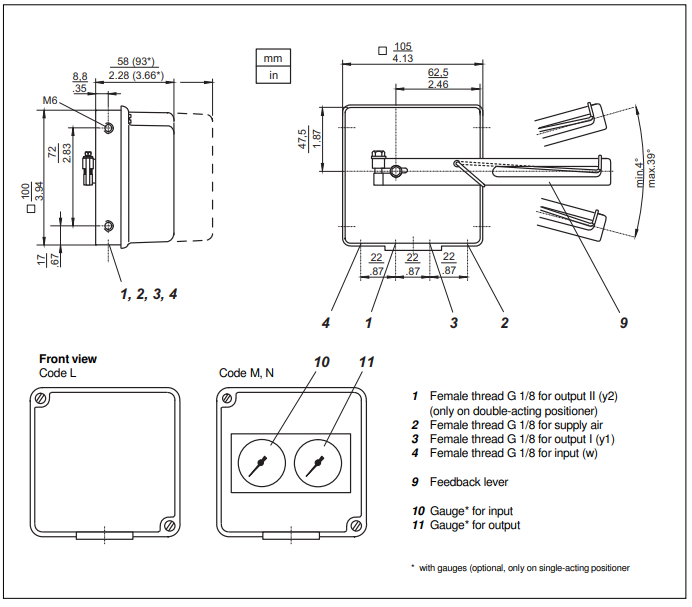
Gauges
| Indicating range | |
| Input | 0 to 1.6 bar (0 to 23 psig) |
| Output | 0 to 10 bar (0 to 150 psig) |
| Error limit | class 1.6 |
Accessories
Connection Manifold With Gauges Code J, M
| Indicating range | 0 to 10 bar (0 to 150 psig) |
| Error limit | class 1.6 |
| Pneumatic connections | Female threads Q 1/4-18 NPT acc. to DIN 45 141 |
Connection Manifold with Gauges Code K, L, N
| Indicating range | |
| Supply, output | 0 to 10 bar (0 to 150 psig) |
| Input | 0 to 1.6 bar (0 to 23 psig) |
| Error limit | class 1.6 |
| Pneumatic connections | Female threads Q 1/4-18 NPT acc. to DIN 45 141 |
Additional Equipment
(built-in into basic device)
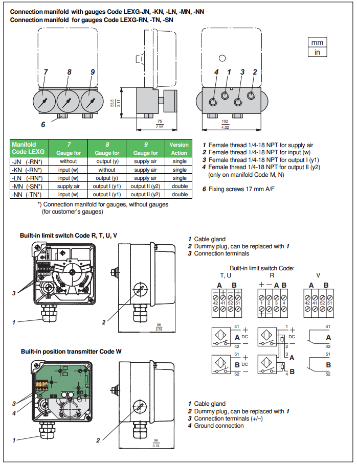
Inductive Limit Switch
Code T, U Two-wire System
| Input | Stroke / angle from actuator via positioner feedback lever |
| Output | 2 inductive proximity sensors acc. to DIN 19234 or NAMUR for connection to a switching amplifier with an intrinsically safe control circuit |
| Current consumption | Vane clear > 3 mA Vane interposed < 1mA |
For control circuit with the following electrical values
| Supply voltage | DC 8 V, Ri approx. 1 kOhm |
| Residual ripple | < 5 % |
| Permissible line resistance | < 100 Ohm |
Response characteristic
| Gain | Continuously adjustable from 1:1 to approx. 7:1 |
| Switching differential | < 1 % |
| Switching point repeatability | < 0.2 % |
Inductive Limit Switch
Code R Three-wire system
| Input | Stroke / angle from actuator via positioner feedback lever |
| Output | 2 inductive proximity sensors, three-wire system, LEDindication, contact, pnp |
| Supply voltage Us | DC 10 to 30 V |
| Residual ripple | ±10 %, Us = 30 V |
| Switching frequency | 2 kHz |
| Constant current | 100 mA |
Response characteristics
| Gain | Continuously adjustable from 1:1 to approx. 7:1 |
| Switching differential | < 1 % |
| Switching point repeatability | < 0.2 % |
Parts set for later installation
| Code R | EW 419 510 291 |
Limit Switch Assembly with Micro switches
Code V
| Input | Stroke / angle from actuator via positioner feedback lever |
| Output | 2 micro-switches |
Connected load
| Alternating current | |
| Switching capacity | max. 250 VA |
| Switching voltage | max. 50 V |
| Switching current with ohmic resistance | max. 5 A |
| inductive resistance | max. 2 A |
| Bulb, metal filament | max. 0.5 A |
Direct Current
| Switching voltage, max | Ohamic load | Inductive load |
| 30 V 50 V |
5 A |
3 A 1 A |
Response Characteristic
| Gain | Continuously adjustable from 1:1 to approx. 7:1 |
| Switching differential | < 2.5 % |
| Switching point repearability | < 0.2% |
Parts set for later installation
| Code V | EW 420 421 017 |
Electrical Position Transmitter
Code W
| Input | Stroke / angle from actuator via positioner feedback lever |
| Sensor | resistive precision conductive plastic element |
| Stroke range | 15 to 80 mm (0.6 to3.15 in) < 15 mm (0.6 in) on request |
| Angular range | 60 to 120 ° |
| Output | Two-wire system |
| Signal range | 4-20 mA |
| Permitted load | RB max = (US–12 V)/0.02 A (US = supply voltage) |
Power supply
| Supply voltage | DC 12 to 36 V |
| Permitted ripple | < 10 % p.p. |
| Supply voltage dependency | < 0.2 % |
Response characteristic
| Non-linearity with terminal based setting | < 1.0 % F.S. |
| Hysteresis | < 0.5 % F.S. |
| External resistance dependency | < 0.2 % / ∆ RB max |
| Temperature effect | < 0.3 % / 10 K |
Explosion protection
| Type of protection | II 2 G Ex ib/ia IIB/IIC T4/T6 |
| Certificate of conformity | PTB 02 ATEX 2153 |
For operation in certified intrinsically safe circuits with the following maximum values:
| Umax | T4: 30 V | T6: 22 V |
| Imax | T4: 130 mA | T6: 66 mA |
| Pmax | T4: 0,9 W | T6: 0.5 W |
| Internal inductance | 9 µH | |
| Internal capacitance | to earth 10 nF or 6 nF differentia |
Ambient temperature
| Temperature class | T6 | –40 to 40 °C (–40 to 104 °F) |
| T5 | –40 to 55 °C (–40 to 131 °F) | |
| T4 | –40 to 80 °C (–40 to 176 °F) |
Parts set for later installation
| Code W | EW 420 661 115 |
Common Data
Ambient conditions
| Ambient Temperature | –25 to 80 °C (–13 to 176 °F) –40 to 80 °C (–40 to 176 °F) |
| Relative Humidity | up to %100 |
| Operating conditions as per IEC 654-1 | The device can be operated at a class D2 location |
Transport and storage
| Temperature | –40 to 80 °C (–40 to 176 °F) |
| Protection class | IP 54 (IP 65 on request) |
Electrical connection
| Line entry | 1 or 2 cable glands M20x1.5 (others with Adapter AD-...) |
| Cable Diameter | 6 to 12 mm (0.24 to 0.47 in) |
| Screw terminals | Screw terminals for wires up to 2.5 mm2 (AWG 14) |
Materials
| Base plate | Galvanized steel |
| Control vane | Aluminium |
| Setting mechanism | Fiber glass-reinforced polyamide |
Electromagnetic compatibility EMC
| Operating conditions | industrial environment |
Immunity according to
| NAMUR recommendation NE21 | fulfilled |
| EN 61 326 | fulfilled |
| EN 61 000-6-2 | fulfilled |
Emission according to
| EN 55 011, Group 1, Class A | fulfilled |
| EN 61 000-6-2 | fulfilled |
CE marking
| Electromagnetic compatibility | 2004/108/EG |
| Low voltage regulations | w/o Ex: 73/23/EWG fulfilled (with Ex: not applicable) |
Safety
| as per DIN EN 61010-1 (DIN IEC 61010-1) (VDE 0411 part 1) | safety class III |
| overvoltage category | 1 |
| internal fuses | none |
| external fuses | Limitation of power supplies for fire protection has to be observed due to EN 61010-1 9.3. ff. |
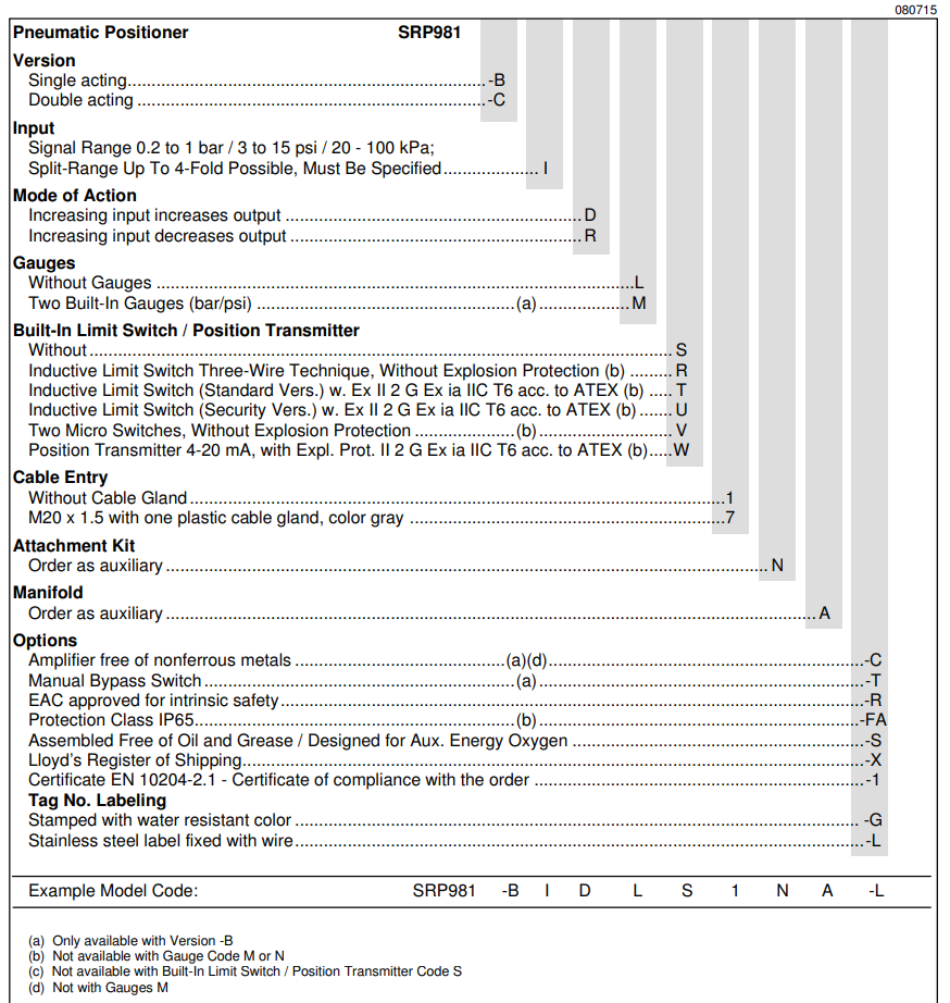
MODEL CODES SRP981
MODEL CODES Accessories
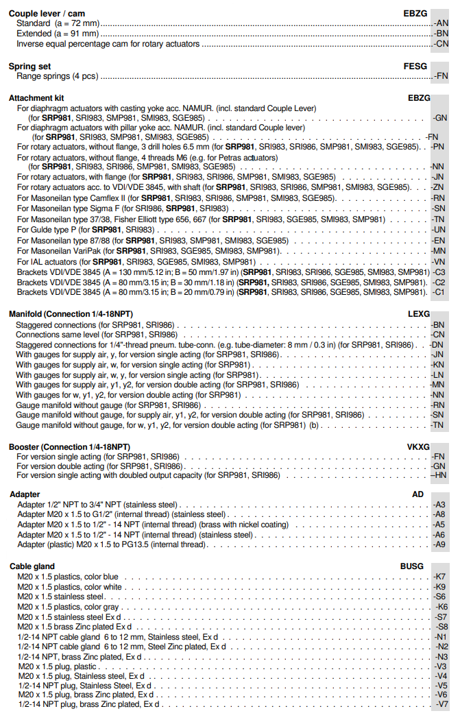
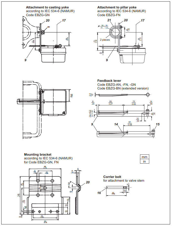
ATTACHMENT KIT FOR DIAPHRAGM ACTUATORS
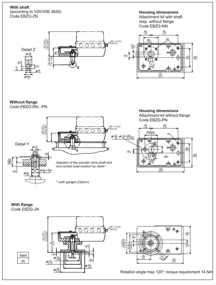
ATTACHMENT KIT FOR ROTARY ACTUATORS
DIMENSIONS Additional equipment
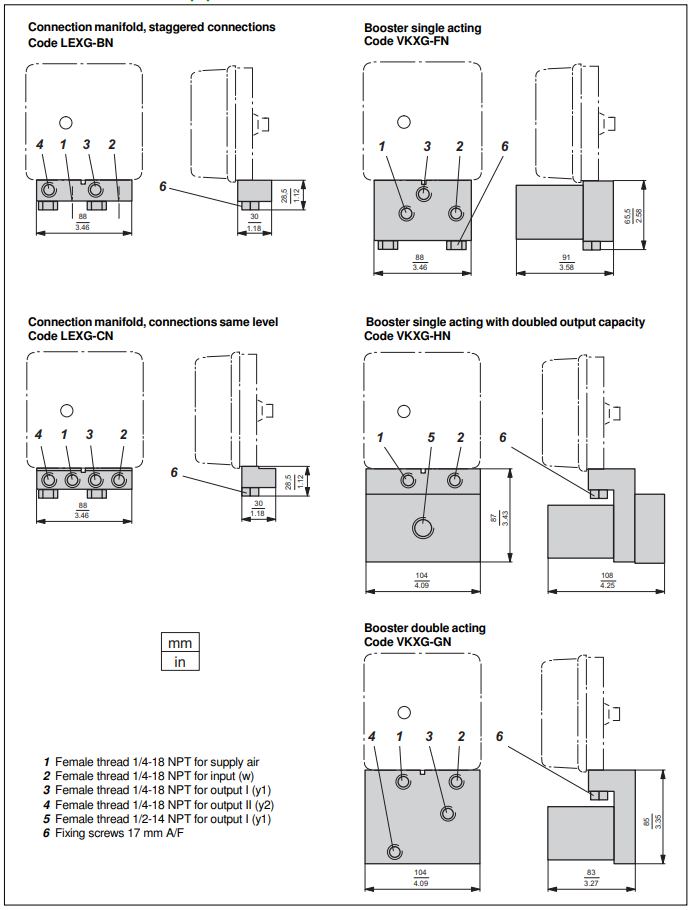
DIMENSIONS Additional equipment
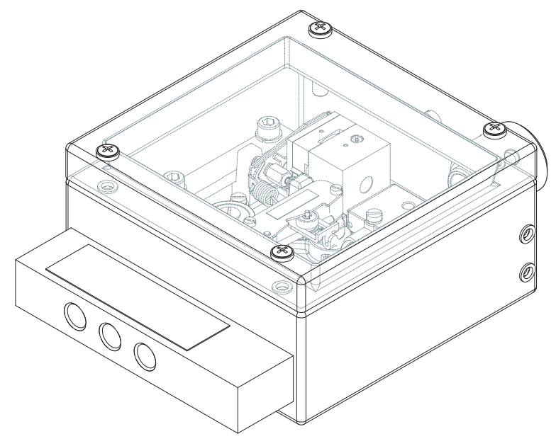
DIMENSIONS SRP981 Special version in Stainless Steel housing
DIMENSIONS, CONNECTIONS
If you require further information on this product or would like a quotation, please contact dp-flow on:
email: [email protected]
sales +44(0)1608 544222