Multivariable Density Compensated Level Transmitter IMV31
The IMV31 Density Compensated Level Transmitter is an intelligent two-wire transmitter. It provides precise and reliable measurement of absolute and differential pressure, sensor and electronics temperature, and process or wet leg temperature. It transmits a 4 to 20 mA or digital output signal using HART Communication Protocol for remote configuration, calibration, and monitoring. When used for tank level measurement, it calculates level compensated for liquid density changes.
Even when fluid density varies, the IMV31 provides accurate tank level measurement. It delivers that accuracy in both open (vented) or closed (pressurized) vessels. Used with fluids of known composition, it compensatesfor density changesin the liquid, the vapor above the liquid, and in the vapor or liquid in any external legs. The result is precise, density-compensated liquid level measurement. The IMV31 is ideal for applications such as boiler drum level where accurate, density-compensated measurement is critical.
FEATURES AND BENEFITS
- One transmitter measures differential pressure, tank pressure, and fluid temperature. This enhances reliability due to fewer transmitters; and also reduces valve, wiring, and installation costs.
- Compensates for liquid density variations caused by both pressure and temperature changes. This provides accurate DP-based level measurement even when liquid density varies.
- Working pressures to 6.9 MPaa (1000 psia) for non boiler applications. Much higher working pressures for boiler applications are as listed in the Functional Specifications section.
- Suitable for open (vented) and closed tanks.
- On closed tanks, equations compensate for dry or wet leg applications. Density compensation also provided for both tank and wet leg liquid.
- Used with nearly any height tank or liquid density.
- Provides cost-effective density-compensated level measurement for numerous process fluids; excellent value for highly functional device.
- Unique selections for water/steam provided to facilitate boiler drum selection/configuration, where accuracy depends on compensating the measured DP for liquid/vapor density changes.
- Standard 5-year warranty.
- Complete configuration capability with Model PCMV configurator, which has a database with extensive fluid properties. Limited configuration with HART Communicator or optional LCD indicator with pushbuttons.
- Reduced process penetrations save money and reduce chances of fugitive emissions.
- Level values from transmitter eliminate need for other resources for level calculations.
- CE marked; complies with EMC, ATEX, and PED European Directives; and NAMUR NE 21
- Interference Immunity requirement. Versions available to meet agency flameproof and zone requirements.
- Dual Seal certified by CSA to meet ANSI/ISA 12.27.01-2003 requirements.
I/A Series PRESSURE TRANSMITTER FAMILY
The IMV31 is part of a complete family of Foxboro gauge, absolute, d/p Cell®, multirange, multivariable, and premium performance transmitters, as well as transmitters with remote or direct mount pressure seals. They all use field-proven silicon strain gauge sensors and common topworks.
EXCEPTIONALLY HIGH PERFORMANCE
Level accuracy to ±0.30% of maximum level
Tank pressure and DP accuracy to ±0.05% of Span
Long term stability with drift less than ±0.05% URL per year over a 5-year period
Minimized static pressure effect on DP by using pressure to compensate the DP measurement
Excellent ambient temperature effect compensation due to characterization and microprocessor-based compensation
Total Probable Error (TPE) significantly better than typical competitive transmitters
MULTIPLE MEASUREMENTS AND CALCULATIONS
Tank Pressure
Differential Pressure (DP)
Fluid Temperature from external RTD
Tank Liquid Level
Tank Liquid Density
Sensor Temperature
Electronics Temperature
DIGITAL HART AND 4 TO 20 mA DC
4 to 20 mA with HART communications allows direct analog connection to common receivers while still providing full digital communicati
ons using a HART Communicator, PC-based configurator, or optional LCD indicator with on-board pushbuttons. For complete configuration capability, Foxboro Model PCMV PC-based configurator is required. A HART Communicator, PC-based configurator, or optional LCD indicator with pushbuttons can be used for routine transmitter functions such as rezeroing or changing damping settings. See Figure 13 for more information on the LCD digital indicator (Option -L).
OPTIONAL CUSTOM FACTORY CONFIGURATION (OPTION -C2)
Changes can be made to the IMV31 using a HART Communicator, PC-based configurator, or optional local display. These configuration methods cannot configure the IMV31 for a specific application, but can only modify some parameter values after the initial configuration. Therefore, Invensys recommends that IMV31 transmitters be factory configured at time of shipment if the application information is known. To supply the necessary information to the factory, the Factory Configuration Option -C2 Configuration Wizard must be run and the results must be available to BuyAutomation. If Option -C2 is not selected in the Model Code, the user must then have Model PCMV configuration software to fully configure the IMV31 transmitter for a liquid level application. The Device Descriptions and Device Type Manager files available from Invensys can modify some configuration parameters, but only the Model PCMV will calculate the necessary coefficients related to the process liquid and pass them to the transmitter.
TANK LEVEL MEASUREMENT AND THE IMV31
When using pressure or differential pressure transmitters to measure tank liquid level, determining the liquid density is important to accurately calculate the level for a given liquid head pressure. With closed tanks that may have a pressure above the liquid that is different from atmospheric pressure, a dry leg, wet leg, or diaphragm seal system may be used to port the top-of-tank pressure to the opposite side of a differential pressure transmitter that is connected to the tank to measure level. The density of the vapor above the liquid, and the densities of vapor or liquid in the external piping connecting the transmitter to the tank, will also influence the calculation of level from the measured differential pressure. The IMV31 compensates for these density variations in order to calculate, display, and transmit an accurate liquid level measurement.
Liquid and vapor density calculations are based on the knowledge of the fluid properties, along with an on-line measurement of pressure and temperature. The Model PCMV configurator has an extensive fluid properties database. For fluids not in the database, it also allows entry of known density values for specific fluid pressures and temperatures.
The IMV31 hardware and firmware can accommodate the following tank configurations to determine the appropriate densities, and to provide accurate tank level measurement. The following heights are user-configurable:
H1 = Height from pressure tap to zero level point
H2 = Height from transmitter connection to pressure tap
H3 = Height from transmitter connection to top pressure connection.
Tanks may be open (vented), or they may be closed (pressurized).
Transmitter can be mounted at minimum level, or below minimum level. A level calibration feature provides tank level zeroing independent of transmitter elevation.
If tank is closed, the leg exiting the top-of-tank to transmitter can be either dry or wet.
If it is a dry leg, then density of vapor in dry leg is calculated if configured for a pressure exceeding 20 psia; and used to correct level measurement for vapor density changes.
If it is a wet leg, density of liquid in wet leg is calculated and used to correct the liquid level measurement.
If transmitter is mounted below minimum level, the leg to transmitter from the lower tank connection is assumed to have liquid in it, and its density calculated to correct the liquid level measurement.
One external RTD can be used for tank or leg fluid temperature measurement.
The temperature of the tank liquid and fluid (vapor or liquid) in both external legs going to each side of transmitter can be independently userconfigured to be:
User-entered constants
RTD temperature (tank liquid or leg fluid)
Electronics temperature (from internal sensor)
Sensor temperature (from internal sensor)
Calculated saturation temperature (water)
The temperatures of the vapor above the tank liquid and the tank liquid, are assumed to be equal.
For boiler drum level applications, the user does not have to enter fluid property data since the liquid and vapor are always water.
ANALOG OR DIGITAL TRANSMISSION
The 4 to 20 mA analog output can be assigned to any one of the following variables:
Differential Pressure
Tank Pressure
Liquid Level
Tank Liquid Density (1)
Also, these variables, along with process, sensor, and electronics temperature, can be read digitally using the Model PCMV configurator or HART Communicator.
The digital output can be used for direct communication with an I/A Series System Fieldbus Module (FBM). With HART protocol, the above listed variables are digitally communicated to the system FBM along with the 4 to 20 mA current.
EASE OF INSTALLATION
Rotatable Topworks
Allows installation in tight places
Positions indicator in preferred direction
Eases field retrofit
Two conduit connections
Provide for easy wiring
Allow self-draining of condensation
Wiring guides and terminations
Provide easy entry and plenty of space
Use large, rugged screw terminals for easy wire termination
PROCESS CONNECTORS
Removable, gasketed connectors allow a wide range of selections, including 1/4 NPT, 1/2 NPT, Rc 1/4, Rc 1/2, and weld neck connectors.
MODEL PCMV MULTIVARIABLE TRANSMITTER CONFIGURATOR
Windows-based software package to configure and calibrate the IMV31 Transmitter for liquid level applications.
Configurator provides for user configuration of tank parameters such as height values, units of measure, and fluid data.
Determines a set of application-specific coefficients to be downloaded to transmitter for use in the transmitter’s equations.
A modem for use with HART protocol or an I/O module passthrough mechanism is required for communication with the transmitter. Refer to PSS 2A-1Z3 F for specifications relating to the Model PCMV Multivariable Transmitter Configurator.
UNIQUE PROCESS COVER AND CELL BODY DESIGN
Biplanar Construction (Figure 6) maintains the traditional horizontal process connections and vertical mounting by providing a cell body contained between two process covers, while still achieving light weight, small size, and high static pressure rating. This provides easy retrofit of any conventional differential pressure transmitter, and also is easily mounted in the horizontal position with vertical process connections, when required.
Process Covers are fully supported by the cell body over their entire height. This prevents bending and results in a highly reliable seal. Also, this provides dimensional stability to the process covers, ensuring that they will always mate properly with 3valve bypass manifolds.
Process Cover Bolts (Figure 6) are enclosed to minimize corrosion and to minimize early elongation with rapid temperature increases. The design makes it less likely for the transmitter to release process liquid during a fire.
Process Cover Gaskets are ptfe as standard; ptfe provides nearly universal corrosion resistance, and eliminates the need to select and stock various elastomers to assure process compatibility.
ATEX Flameproof Design allows the transmitter to be installed in hazardous locations requiring ATEX Flameproof rating.
Light Weight provides ease of handling, installation, and direct mounting without requiring costly pipe stands.
TRADITIONAL STRUCTURE
The traditional structure utilizes the right angle design common to most differential pressure transmitters in use throughout the world. Process connections are oriented 90 degrees from the transmitter centerline. This traditional structure makes it easy to retrofit any transmitters of similar design.
Sensor cavity venting and draining is provided for both vertical and horizontal transmitter installation, using innovative tangential connections to the sensor cavity. Optional side vents are offered for sensor cavity venting in the upright position.
An extensive variety of process-wetted materials are available for the process covers on this highly versatile and widely used transmitter.
Output Signal and Configuration
One 4 to 20 mA output with HART Communications. This 4 to 20 mA output applicable to level (or other) measurements. When configured for multidrop applications, the mA signal is fixed at 4 mA to provide power to the device.
Configurable with a HART Communicator, Model PCMV Configurator, or optional LCD indicator with on-board pushbuttons. Model PCMV Configurator required for complete level configuration.
Tank Outputs
Tank Pressure
Differential Pressure
Sensor Temperature (from Internal Sensor)
Electronics Temperature (from Internal Sensor)
Fluid Temperature (from External RTD)
Tank Liquid Level
Tank Liquid Density
Level Units
Inches
Feet
Millimeters
Centimeters
Meters
Adjustable Damping (DP and Pressure)
The transmitter response time is normally 1.0 s, or the electronically adjustable setting of 0.00 (none), 0.25, 0.50, 1, 2, 4, 8, 16, or 32 seconds, whichever is greater, for a 90% recovery from an 80% input step as defined in ANSI/ISA S51.1.
Field Wiring Reversal
No transmitter damage.
Minimum Allowable Absolute Pressure vs. Transmitter Temperature
With Silicone Fill Fluid Full vacuum: up to 121 °C (250 °F)
Zero and Span Adjustments
Zero and span adjustments can be initiated from the PCMV Configurator or optional LCD indicator with onboard pushbuttons. Zero and span adjustments are provided for level, differential pressure, and pressure. Zero adjustment is provided for temperature measurements.
Zeroing for Nonzero-Based Ranges
Dual Function Zeroing from the optional LCD indicatorpushbuttons allows differential pressure zeroing with either zero differential or LRV differential applied. This simplifies position effect zeroing. Also, the PCMV or HART Communicator provides zeroing at any user entered value.
Supply Voltage
Nominal minimum supply voltage is 11.5 V dc.
Write Protect Jumper
Can be positioned to lock out all configurators from making transmitter database changes. This makes transmitter suitable for safety shutdown system applications that require this feature.
Process Temperature Measurement and Limits
Measurement: DIN/IEC, 2-, 3-, or 4-wire, 100 ohm, Platinum RTD
Range Limits: -200 and 850°C (-328 and 1562°F)
Communications
Configurable for either 4 to 20 mA or multidrop. Digital communications is provided in all modes based upon the FSK (Frequency Shift Keying) technique which alternately superimposes one of two different frequencies on the uninterrupted current carried by the two signal/power wires. See Table 1 for HART communication parameters.
Configuration and Calibration Data, and Electronics Upgradeability
All factory characterization data, and user configuration and calibration data, are stored in the sensor. This means that the electronics module can be replaced without requiring transmitter reconfiguration or recalibration. Although module replacement can affect accuracy up to 0.20% of span, this error can be removed by an mA trim without application of pressure.
Option -C2: Optional Custom Factory Configuration
Invensys recommends that the IMV31 be factory configured by selecting Option -C2, and completing the Multivariable Configuration Wizard before entering the order. If Option -C2 is not selected, a standard default configuration will be provided. The user will then need to completely configure the transmitter for liquid level applications using the Model PCMV.
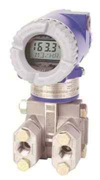
Option -L1: Optional Liquid Crystal Display (LCD) Indicator with On-Board Pushbuttons
Indicator provides: Two Lines; five numeric characters on top line (four when a minus sign is needed) and seven alphanumeric characters on bottom line.
Measurement Readout; value displayed on top line, and units label displayed on bottom line.
Configuration and Calibration Prompts.
Pushbuttons provide for:
Configuration (2) Functions
Calibration Functions
PERFORMANCE SPECIFICATIONS
Zero-Based Calibrations; Stainless Steel Sensor with Silicone Fluid; Under Reference Operating Conditions unless otherwise specified; URL = Upper Range Limit and Span = Calibrated Span
Accuracy - Differential Pressure (a) (b)
| Span Codes | Accuracy in % of Span Spans ≥10% URL |
Spans < 10% URL |
|---|---|---|
| B and C | ±0.05 | ±(0.005) (URL/Span) |
| A | ±0.10 | ±(0.010)(URL/Span) |
(a) Accuracy stated includes the effects of linearity, hysteresis, and repeatability.
(b) Also add ±0.025% to the accuracy to determine the total analog output accuracy if the DP measurement is assigned to the 4 to 20 mA output signal.
Accuracy - Absolute Pressure (a) (b)
| Span Codes | Accuracy in % of Span Spans ≥10% URL |
Spans <10% URL |
|---|---|---|
| D, E, H and F | ±0.05 | ±(0.005) (URL/Span) |
| Span Codes | Accuracy in % of Span Spans ≥5% URL |
Spans <5% URL |
| A | ±0.05 | ±(0.0025)(URL/Span) |
Accuracy - Process Temperature
±0.28°C (±0.5°F) within ±140°C (±250°F) of the normal operating point.
Accuracy - Level Measurement
±0.3% of maximum level, based on the following:
Density and level calculations are based on published AP and DP accuracies and include ambient temperature effects over a range of ±28°C (±50°F).
Liquids and vapors are selected from the list of over 275 fluids in the PCMV Configurator Fluid Properties Database or, if the fluid is not listed, the transmitter has been configured for a known variation of fluid density with pressure and temperature.
The source of each applicable fluid temperature is configured to be RTD, sensor temperature, electronics temperature, or a user-entered value, and these temperatures are representative of the fluid temperatures.
Optimal sensor span code is selected so that the lowest URL that meets the application is used.
Stability
Long-term drift less than ±0.05% of URL per year over a 5-year period.
Calibration Frequency
The calibration frequency is five years. The five years is derived using the values of allowable error (% span), TPE (% span), performance margin (% span), and stability (% span/month);
where: Calibration Frequency = Performance Margin / Stability = Months
Power-up Time
Less than 5 seconds for output to reach first valid measurement.
Vibration Effect
±0.2% of URL per “g” for vibrations in the range of 5 to 500 Hz; with double amplitudes of 6.3 mm (0.25 in) in the range of 5 to 15 Hz, or accelerations o3 “g” in the range of 15 to 500 Hz, whichever is smaller, for aluminum housings; and with double amplitudes of 6.3 mm (0.25 in) in the range of 5 to 9 Hz, or accelerations of 1 “g” in the range of 9 to 500 Hz, whichever is smaller, for 316 ss housings.
RFI Effect
The output error is less than 0.1% of span for radio frequencies in the range of 27 to 1000 MHz and field intensity of 30 V/m when the transmitter is properly installed with shielded conduit and grounding, and housing covers are in place. (Per IEC Std. 61000-4-3.)
Supply Voltage Effect
Output changes less than 0.005% of span for each 1 V change within the specified supply voltage requirements.
Ambient Temperature Effect
Total effect for both absolute and differential pressure for a 28°C (50°F) change within Normal Operating Condition Limits is ±(0.03% URL + 0.06% span); except the effect on differential pressure for DP Span Code A is ±(0.18% URL + 0.025% span). Also for AP Span Code H, the effect is ±(0.02% URL + 0.06% span).
Position Effect
Transmitter may be mounted in any position. Any zero effect caused by mounting position can be eliminated by rezeroing. There is no span effect.
Switching and Indirect Lightning Transients
The transmitter can withstand a transient surge up to 2000 V common mode or 1000 V normal mode without permanent damage. Output shift is l.t. 1.0%.
(Per ANSI/IEEE C62.41-1980 and IEC Std. 61000-4-5.)
Electromagnetic Compatibility
Complies with NAMUR NE 21 Interference Immunity Requirement (EMC) Complies with electromagnetic compatibility requirements of European EMC Directive 89/336/EEC by conforming to following CENELEC and IEC Standards: EN 50081-2, EN 50082-2, IEC 61000-4-2 through 61000-4-6.
PHYSICAL SPECIFICATIONS
Process Cover and Connector Material (Process Wetted)
316 ss or nickel alloy (equivalent to Hastelloy® C (3)), as specified.
Process Cover and Process Connection Gaskets
Glass filled ptfe (Chemloy)
Process Cover Bolts and Nuts
ASTM A193, Grade B7 high strength alloy steel for bolts, and ASTM A194 Grade 2H high strength alloy steel for nuts are standard. Options include NACE Class II - B7M bolting, 17-4 ss bolting, and 316 ss bolting. NACE Class II is recommended when bolting is directly exposed to sour environments, or is buried, insulated, or otherwise denied atmospheric exposures.
Sensor Material (Process Wetted)
316L ss or nickel alloy (equivalent to Hastelloy C), as specified
Sensor Fill Fluids
Silicone Oil or Inert (FC-43)
Environmental Protection
Transmitter is dusttight and weather proof per IEC IP66 and provides the environmental and corrosion resistant protection of NEMA Type 4X.
Electronics Module
Printed wiring assemblies are conformally coated for moisture and dust protection.
Electronics Housing and Housing Covers
Housing has two compartments to separate the electronics from the field connections. The housing and covers are made from low copper, die-cast aluminum alloy with an epoxy finish, or from 316 ss. Buna-N O-ring seals are used to seal the threaded housing covers, housing neck, and terminal block.
Electrical Connections
Field and RTD sensor wires enter through 1/2 NPT, PG 13.5, or M20 threaded entrances, as specified, oneither side of the electronics housing. Wires terminate under screw terminals and washers on terminal block in the field terminal compartment.
Mounting Position
The transmitter may be mounted in any orientation.
Approximate Mass
3.5 kg (7.8 lb) – without Process Connectors
4.2 kg (9.2 lb) – with Process Connectors
Add 1.1 kg (2.4 lb) – with 316 ss Housing
Add 0.2 kg (0.4 lb) – with LCD Indicator Option
Absolute pressure range
IAP10, IAP10S, IAP20,
Differential pressure range
IDP10, IDP15, IDP25, IDP31, IDP32, IDP50
Gauge pressure range
IGP10, IGP10S, IGP20, IGP25, IGP50, IGP60
Multi variable transmitter range
IMV25, IMV30, IMV31
If you require further information on this product or would like a quotation, please contact dp-flow on:
email: [email protected]
sales +44(0)1608 544222
Supplied by DP-Flow