Pneumatic Buoyancy Transmitter with Torque Tube for Liquid Level, Interface and Density167LP
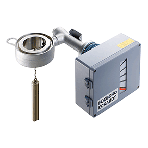
The pneumatic buoyancy transmitter 144LVD measures liquid level, interface or density with displacer (Archimedes principle) and torque tube as transmitting element.
NATIONAL SAFETY ASPECTS OF LEVEL TRANSDUCERS
The pressurized parts of measuring transducers for liquid levels are designed in accordance with the recognized rules of technology.
Use in the explosion-risk area of Zone 0.
In accordance with test certificate 01/PTB/III B/S 1506, the pneumatic transducers type BF 628 may be used to indicate the liquid levels in stationary tanks for the storage of combustible liquids in groups and danger classes A I, A II and B, danger area 0, with the exception of carbon bisulfide. The “Special requirements” on the test certificate must be observed!
Use as part of the overflow protection liquids to VbF.
In accordance with certificate 01/PTB/III B/S 1698 F the pneumatic transducer, Type BFF 628, may be used as part of the overflow protection for avoidance of overflow in stationary tanks for combustible liquids, danger classes A I, A II, A III and B, with the exception of carbon bisulfide, and for use in Zone 0. The “Special requirements” on the test certificate must be observed!
The parts of the system used for overflow protection and not having a certificate must conform with the requirements of Nos. 3 and 4 of TRbF 510, Annex 1. The overflow protection units must be installed and operated in accordance with the requirements of TRbF 510, Annex 1.
Use as part of the overflow protection for non-combustible liquids
In accordance with approval mark Z-65.11-21 the pneumatic transducer, Type BWF 628, may be used as part of the overflow protection for stationary tanks for storage of non-combustible liquids hazardous to water. The “Special requirements” on the test certificate must be observed!
The parts of the system used for overflow protection must conform with the requirements in Sections 3 and 4 of the Design and Test Regulations for Overflow Protection. The overflow protection units must be installed and operated in accordance with the requirements of Annex 1, “Setting instructions for overflow protection for tanks”, and Annex 2, “Installation and operating guidelines for overflow protection” of the Design and Test Regulations for Overflow Protection.
Use in steam boiler systems as a second water level transducer subject to license
According to the VdTÜV brochure “Water Level 252”, component identification TÜV WRS 84-252 (79-252) the transducer may be used as a second water level transducer subject to license in land-type steam boilers. In the event of a faillure or malfunction in the auxiliary energy, there must be a guarantee, for example via a pressure switch in the supply line, that the firing system and the supply water pump are switched off. Transducers with displacer vessel with side-to-side or side-to-top vessel connections which have been manufactured in accordance with the component drawing, may only be used.
Use in steam boiler systems
In accordance with § 2 of Article 1 “Ordinance on Steam Boiler Systems” of the “Ordinance superseding Ordinances in accordance with § 24 of the Industrial Code” of 27.02.80, liqiud level transducers are equipment parts within the scope of this ordinance. They must be subjected to a design and pressure test by the fittings manufacturer in accordance with TRD 110 Fittings Group 5. The materials used must correspond to the technical rules applicable to steam boilers (TRD). By marking the fittings in accordance with TRD 110, Point 5.1, the fittings manufacturer guarantees that the fittings correspond to TRD 110 Fittings Group 5. The material certificates are in the possession of the manufacturer.
Use on pressure tanks
In accordance with § 3 of Article 2 “Ordinance on pressure tanks, pressurized gas containers and filling systems” of the “Ordinance superseding Ordinances in accordance with § 24 of the Industrial Code” of 27.02.80, liquid level transducers are not independent pressure tanks. They are equipment parts of pressure tanks in accordance with the Ordinance if they can influence the equipment parts necessary for safety when installed as measurement and control devices on the pressure tank. They are not subject to this Ordinance if they cannot influence equipment parts necessary for safety reasons installed as devices on pressure tanks.
Therefore, liquid level transducers must be classified by the user of the system.
The pressurized parts of transducers in accordance with AD brochure A4 “Housings of fittings” are designed as equipment parts on pressure tanks within the scope of this Ordinance. In accordance with the AD brochure A4 “Housings of fittings” liquid level transducers are subject to a design and pressure test by the fittings manufacturer. The materials of the pressurized parts used must correspond with the permissible materials in accordance with the AD brochures, series W. Quality evidence is guaranteed by the acceptance test certificate 3.1 B DIN 50049. The certificates are in the hands of the manufacturer. By identifying the fittings in accordance with AD-A4, Point 7.2, the fittings manufacturer confirms that the materials used, the manufacturing and testing methods for the fittings comply with the AD brochure A4. If so wished by the user, the acceptance test (pressure test) of the fitting can also be carried out by an idependent expert.
FEATURES
- Level transmission between vessel and transmitter by torque tube
- Applicable for service temperatures from –196 °C to +400 °C and pressures up to PN 250
- The span can be set over a 1:5 ratio
- A wide selection of materials facilitates service under corrosive conditions
- Material opproval certificates acc. to EN 10204-3.1 available
- Various licences in accordance with national regulations
TECHNICAL DATA
In accordance with standard DIN IEC 770, data refer to the sensor material Type 316L (1.4404)
- Input
- Measuring span. . . . . . . . . . 3 1) to 15 N
- Density range 2) . . . . . . . . . . 100 < ? < 1600 kg/m3
- Standard lengths of displacers 3) . . . . . . . . . . . . . 350 to 3000 mm 14 to 120 inch
- Weight of displacer 4) . . . . . . max. 25N
- Output . . . . . . . . . . . . . . . . 0.2 to 1 bar / 3 to 15 psi / 20 to 100 kPa / 0.2 to 1 kp/cm2
- Supply air . . . . . . . . . . . . . 1.4 ± 0.1 bar or 20 ± 1.4 psi
- Operating conditions
- Process temperature 5) 6) . . . –196 °C to +400 °C
- Pressure rating
- acc. toDIN . . . . . . . . . . . . PN16, 40, 63, 100, 160, 250
- acc. to ANSI . . . . . . . . . . . Class 150, 300, 600, 900, 1500
- with heating jacket 8) . . . . . wafer body max. PN 160 / Class 900; heating jacket PN 25, heating with saturated steam or thermal oils
- Ambient temperature 9). . . . . –40 to +90 °C
- Relative humidity . . . . . . . . . = 100 %
- Condensation . . . . . . . . . . . permitted
- Transportation and storage temperature. . . . . . . –40 to +90 °C
- Protection class . . . . . . . . . . IP 55 (acc. toDIN40 050)
- The device can be operated at a class D2 location in accordance with DIN IEC 654, part 1.
- Transitional behaviour
- Relative error . . . . . . . . . . . . =1%
- Sensitivity . . . . . . . . . . . . . . < 0.1%
- Ambient temperature influence . . . . . . . . . . . . . . . = 0.2%/10 K
- Process temperature influence . . . . . . . . . . . . . . . = 0.1%/10 K
- Supply air influence . . . . . . . = 0.2 %/0.1 bar
- Air consumption. . . . . . . . . . = 200 l/h
- Air capacity . . . . . . . . . . . . . 1200 l/h
- Load effect (measured at 0.6 bar). . . . . . +3%for400l/hexhaused flow –3 % for 400 l/h delivered flow
Mounting
- Mounting method . . . . . . . . . sandwich mounted
- acc. toDIN . . . . . . . . . . . . DN80,DN100
- acc. to ANSI . . . . . . . . . . . 3 inch, 4 inch
- Pneum. connections. . . . . . . internal thread DIN 45 141-Q1/4-18 NPT
For Sour Gas applications according to NACE Standard MR-0175-92:
- Wafer body . . . . . . . . . . . . 316L (1.4404)
- Torque tube . . . . . . . . . . . HastelloyCor Inconel 600
Weight
- Head with transmitter housing
- without heating jacket . . . . 15 kg (Class 1500 18.5 kg)
- with heating jacket. . . . . . . 16 kg
Additional equipment
- Oil damping in the transducer unit in the event of excessive acceleration (> 2 g; > 20 Hz)
If you require further information on this product or would like a quotation, please contact dp-flow on:
email: [email protected]
sales +44(0)1608 544222
Supplied by DP-Flow