Intelligent Buoyancy Transmitter for Liquid Level, Interface and Density 144LVD
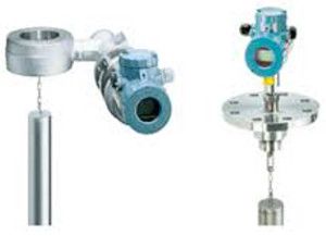
The intelligent transmitter 144LVD is designed to perform continuous measurements for liquid level, interface or density of liquids in the process of all industrial applications. The measurement is based on the proven Archimedes buoyancy principle and thus extremely robust and durable. Measuring values can be transferred analog and digital. Digital communication facilitates complete operation and configuration via PCor control system. Despite high process pressure and corrosive liquids, the 144LVD measures with consistent reliability and high precision. For installations in contact with explosive atmospheres up to Zone 0, certificates are available. The 144LVD combines the abundant experience of FOXBORO ECKARDT with most advanced digital technology.
FEATURES
- Communication HART, FoxCom, PROFIBUS PA or FOUNDATION Fieldbus
- Conventional operation with local keys
- Easy adaptation to the measuring point without calibration at the workshop
- Backdocumentation of measuring point
- Continuous self-diagnostics
- Configurable safety value
- Software lock for local keys and reconfiguration
- Approved for SIL2 applications
- Simulation of analog output for loop-check
- Local display in %, mA or physical units
- Signal noise suppression by Smart Smoothing
- Linear or customized characteristic
- Process temperature from -50 °C to +120 °C
- Materials for use with aggressive media
- Micro sintermetal sensor technology
- Separate mounting of sensor and amplifier with remote amplifier mounting kit
DESIGN
The transmitter is based on a modified differential pressure measuring cell. The sensor is a flexure beam, which is mechanically linked to the measuring diaphragm, so the measuring cell also can be used for force measurement. The static pressure effects both sides of the measuring cell and does not influence the measurement.
METHOD OF OPERATION
The buoyancy force of the displacer is transferred via transmission lever and torque tube to operating rod of the sensor, where it acts on free end of sensor element. Four thin film metal strain gauge elements are sputtered onto sensor element, which change their resistance in the ratio of the tensile or pressure tension. These four thin film metal strain gauge elements are connected as a Wheatstone full bridge supplied from amplifier. The voltage at the diagonal bridge section which is proportional to the effective weight is fed to the electronic amplifier as an input signal. This voltage is converted via the electronic amplifier into the 4 to 20 mA or digital two-wire output signal. The amplifier is supplied by the signal current circuit in twowire mode.
Measuring principle
Any body immersed into a liquid is subject to Archimedian buoyancy force which depends on the liquid density. This is exploited to determine liquid level, density and interface level by suspending a displacer with constant cylindric shape into a liquid. Changes in buoyancy forces are proportional to liquid level changes and are converted to a measuring signal. The displacer is fully immersed for density and interface level detection. It is important that the position of the displacer changes as little as possible over the measuring range.
TECHNICAL DATA
Data refer to the sensor material Type 316L (1.4404)
Explosion protection certificates must be observed!
- Input / Output
- Measuring ranges . . . . . . . . 50mmto 50m upper and lower range value continuously adjustable
- Standard lenghts of Displacer (104DE) . . . . . . . . 350 .. 3000 mm, 14 .. 120 in; further lenghts on request
- Weight of displacer 1) . . . . . . max. 40N
- Measuring span. . . . . . . . . . 2... 20Ncontin. adjustable (to 1 N on request)
- Span ratio
- Turn-down . . . . . . . . . . . . . . 1:1 .. 1:10 (1:20 on request)
- Accuracy 2) . . . . . . . . . . . . . ± 0.2 % ; increased accuracy with customized adjustment
- Transfer function . . . . . . . . . linear or customized with up to 32 setpoints 3)
- Configuration
- - with local push buttons and LCD
- - Digital (see communication ...)
- Local display . . . . . . . . . . . . LCD5 digits, configurable in %, mA or phys. units
- Load . . . . . . . . . . . . . . . . . RBmax = (US – 12V) / 23 mA
Operating conditions
- Process temperature . . . . . . –50 °C... +120 °C
- Pressure rating
- acc. toDIN . . . . . . . . . . . . PN16, 40, 63, 100, 160, 250, 400, 500 3)
- acc. to ANSI . . . . . . . . . . . Class 150, 300, 600, 900, 1500, 2500 3)
- Ambient temperature 4) 5)
- without indicator . . . . . . . . –40 °C... +85 °C
- with LCDindicator. . . . . . . –40 °C... +70 °C6)
- Relative humidity . . . . . . . . . < 100%
- Condensation . . . . . . . . . . . permitted
- Transportation
- storage temperature. . . . . . . –50 °C ... +85 °C
- Protection . . . . . . . . . . . . . . IP 66 (acc. DINEN60 529)
- Operation condition effects
- Ambient temperature . . . . . . –10 °C... +70 °C
- Zero. . . . . . . . . . . . . . . . < 0.1%/ 10 K7)
- Span . . . . . . . . . . . . . . . < 0.07%/ 10 K
- Process temperature . . . . . . < 0.1%/ 10 K 7)
- Operating pressure . . . . . . . < 0.2%of upper measured value (with PN 500)
Transitional behavior
- Dynamic behavior
- Damping (90%-time) . . . . . 0 ... 32 s
- Switch-on time . . . . . . . . . 7 s
- Step response (63%-time) with damping 0 s. . . . . . . . 250ms
- Update rate . . . . . . . . . . . . . 10/s
- Long term stability . . . . . . . . < 0.2%/ 6months at 20°C7)
- Noise suppression
- Commonmode voltage. . . < AC250 Veff
- Common mode rejection . . 120 dB
- Seriesmode rejection . . . . 50 dB
- Mains synchronization. . . . 50Hz / 60Hz
- Filter . . . . . . . . . . . . . . . . . Smart Smoothing
If you require further information on this product or would like a quotation, please contact dp-flow on:
email: [email protected]
sales +44(0)1608 544222
Supplied by DP-Flow