
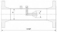
The EMCO EM-CONE Cone type Differential Pressure Producer is used as primary element in flow measurement of liquid, gas and steam according to the differential pressure principle using equations similar to equations for orifices and venturis.
The differential pressure is measured with a differential pressure transmitter between the up stream tapping (+ tapping) in the wall of the cone meter and the down stream tapping (- tapping) in the cone for model EMF CT or in the wall for model EMF-WT
The inlet cone has a good flow con ditioning effect especially for small ß values. This effect supports the short straight pipe run requirements.
Larger size M-CONEs are furnished with vanes for 2 reasons:
1. Better flow conditioning effect.
2. Mechanical support of cone.
Benefits
- Wide range of applications
- Space saving
- Repeatable.
- Ideal for difficult applications.
- Suitable for erosive fluids.
- No risk of clogging. Self cleaning.
- Suitable for wet gas metering.
- Fully in compliance to PED 97/23EC.
Construction
| Design and calculation standards | EN, PED 97/23 EC, ANSI/ASME |
| Sizes | DN 50 - 1000 2” – 40” |
| Pressure rating | PN 10 - 400, 150 - 2500 lbs |
| Material | Carbon steel P235GH, P250GH, A105N, A350LF2, A106 Gr. B, AISI 316, 22 Cr. Duplex, 25 Cr. Duplex, 6Mo, 16Mo3 (F1), 13CrM o4-5 (F11) 10CrMo9-10 (F22), other materials on request |
| Mounting style | Weld ends according to EN 9692-1 or ANSI B16.25. |
| Flanges connection according to DIN, ISO or ANSI. | |
| Hub connection for clamping between hubs (Grayloc). | |
| Pressure taps | ½”, ¾” NPT ext., ½”, ¾” flanged, others on request |
| Flange facing | Flat or raised face according to DIN 2526 or flat, raised face or ring type joint according to ANSI B 16.5 |
| Beta ratio (d/D) | 0,4, 0,5, 0,6, 0,7 and 0,85 (0,7 is standard). |
| D : inner pipe diameter, d : cone diameter |
Beta Ratio
The definition of β for cone meters is different from orifice plates and venturis where β = d/D.
The free area for a given M-CONE is the same as for orifice plates and venturi tubes
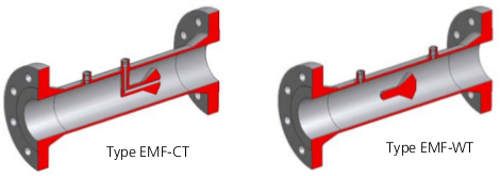
Tapping arrangements
- 2 types of tapping arrangements are available.
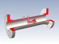
- Type EMF-CT:
- The most common type has the up stream pressure taken from a tapping in the wall of the cone meter and the down stream pressure taken from the down stream side of the cone with an internal line to a tapping in the wall.
- Type EMF-WT
- The most universal one has the up stream as well as the down stream pressure taken from tappings in the wall of the cone meter.
- Whenever there is a risk of trapping air/gas in a liquid flow measurement or liquid/condensate in a gas flow measurement the type EMF-WT should be selected.
Sizes
DIN Flanges
| Tapping selection table. | |||
|---|---|---|---|
| Pipe orientation | |||
| Fluid | Horizontal | Vertical down | Vertical up |
| Liquid | CT or WT | WT | CT or WT |
| Gas | CT or WT | CT or WT | WT |
| Steam | CT or WT | CT or WT | WT |
Pressure loss comparison
The pressure loss of a differential pressure flow meter depends on the mechanical design of the element. More specifically the outlet section of the restriction determines the pressure loss.
DP elements with high pressure recovery have low pressure loss and low pressure recovery elements have high pressure loss.
An orifice plate creates turbulence downstream, consequently the pressure recovery is low and therefore the pressure loss is high.
The classical venturi tube has a high pressure recovery due to the long outlet cone creating a steady velocity decrease and pressure increase. Therefore the classical venture tube has a very low pressure
loss.
The M-CONE cone meter has an outlet cone with a large angle creating some turbulence but certainly not so much as an orifice plate. The pressure recovery for a cone meter is not as high as a classical venturi tube and therefore the pressure loss is higher for a cone meter than a classical venturi tube.
The cone meters do not require pipe line reduction in order to measure correctly in the full range as the Vortex flow meter. This pipe line reduction causes pressure loss. Therefore the pressure loss of a cone meter is lower than a vortex meter.
| Technical Data | |
|---|---|
| Accuracy | +/- 1-2 % (un-calibrated), +/- 0,5 % (calibrated). |
| Repeatability | +/- 0,1 % |
| Pressure loss | 40 % of measured differential pressure with beta ratio 0,7 |
| Limits for Reynolds No. | Re > 10.000, lower Re. Consult factory |
| Installation requirement | Down to 5 x D up-stream and 2 x D down-stream. |
Accessories
- Primary shut-off valves
- Condensing chambers for steam flow measurement.
- Steam jacket (only type EMF-WT)
Overall Dimensions
| DN/Inch | Weld End | 150 lbs | 300 lbs | 600 lbs | 900 lbs | 1500 lbs | 2500 lbs | Hub connection |
|---|---|---|---|---|---|---|---|---|
| 50 / 2” | 275 | 400 | 400 | 450 | - | 500 | 600 | 350 |
| 65 / 21⁄2” | 325 | 450 | 450 | 500 | - | 550 | 600 | 350 |
| 80 / 3” | 360 | 500 | 500 | 550 | 650 | 650 | 750 | 460 |
| 100 / 4” | 400 | 550 | 550 | 600 | 700 | 700 | 800 | 500 |
| 150 / 6” | 570 | 750 | 750 | 800 | 900 | 900 | 1100 | 800 |
| 200 / 8” | 650 | 850 | 850 | 900 | 1100 | 1100 | 1300 | 900 |
| 250 / 10” | 700 | 900 | 900 | 1000 | 1200 | 1200 | 1600 | 1000 |
| 300 / 12” | 770 | 1000 | 1000 | 1100 | 1250 | 1300 | 1700 | 1100 |
| 350 / 14” | 800 | 1050 | 1050 | 1100 | 1250 | 1400 | - | 1200 |
| 400 / 16” | 800 | 1050 | 1050 | 1150 | 1300 | 1400 | - | 1520 |
| 450 / 18” | 820 | 1100 | 1150 | 1200 | 1450 | 1500 | - | 1300 |
| 500 / 20” | 910 | 1200 | 1300 | 1350 | 1600 | 1700 | - | 1400 |
| 600 / 24” | 1195 | 1500 | 1500 | 1600 | 1800 | 1900 | - | 1600 |
| 700 / 28” | 1700 | 1800 | 1900 | 2000 | 2050 | - | - | |
| 800 / 32” | 1700 | 1950 | 1950 | - | - | - | - | |
| 900 / 36” | 1700 | 1950 | 2000 | - | - | - | - | |
| 1000 / 40” | 2000 | 2200 | - | - | - | - | - |
Works with:-Differential pressure transmitters:-IDP10; IDP15; IDP25; IDP31; IDP50
And all our Absolute Pressure and Gauge Pressure transmitters, Temperature sensors and mass flow computers.
MultiVariable Transmitters :- IMV25, IMV30
Download Datasheet Cone type 'EM-Cone' Differential Pressure Flowmeter
Download Manual (Not Available)
If you require further information on this product or would like a quotation, please contact dp-flow on:
email: sales@dp-flow.co.uk
sales +44(0)1608 544222
Supplied by DP-Flow