ST1; ST2; ST3
The EMCO Steemco compact orifice flow meter for steam is a standardised product based on well proven and widely accepted technology. The Steemco meter is a flow orifice assembly designed to slip between DIN and ANSI flanges, and is designed for compact mounted dp cells. With an installation length of 32mm it can be installed in existing systems simply and easily, and incorporates the dp flow priciple. d.p. metering enables easy re-calibration routines for process operators, negating the need for expensive flow metering spares and external flow recalibration services.
Benefits
- Sizes ranging from DN 40 (1½") up to DN 400 (16").
- No moving parts.
- Not sensitive to vibrations.
- Compact design.
- Easy to install.
- High accuracy.
Typical Applications
The STEEMCO flow meters measure the flow of saturated and superheated steam within the process industries, including chemical, petro-chemical, pharmaceutical and the power industry. The STEEMCO is based on the principle of measuring velocity in the pipe line, therefore the flow measurement is volumetric. The STEEMCO flow meters are backed by international standards covering flow calculation, manufacturing tolerances, accuracy and installation requirements. This type of fundamental technology is accepted world wide and supported by millions of successful installations.
The STEEMCO flow meter features are:
- Standardised product based on well proven technology.
- Compact design.
- Simple construction.
- Standardised construction means low inventory.
- No moving parts.
- Not sensitive to vibrations.
- The electronics delivers output signal linear to flow.
- Digital indicator for local flow reading.
- High accuracy.
- Wide rangeability.
- Easy to install.
- Easy to re-calibrate.
Construction
Model ST1
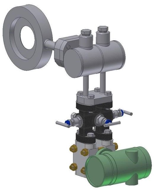
The Steemco flow meter model ST1 consists of a primary element based on the differential pressure principle, condensing pots, a 3 valve manifold valve and an electronic differential pressure transmitter with digital signal processing.
Model ST2
The Steemco flow meter model ST2 consists of a primary element based on the differential pressure principle with an all welded integral condensing pot, an integrated 3 valve double flanged manifold valve and an electronic differential pressure transmitter with digital signal processing. The Steemco flow meter is mounted between flanges in sizes from DN 40 (11⁄2") to DN 400 (16") in pressure ratings up to PN 40 (300 lbs).
Accessories
Remote electronic indicator with LCD is available for local flow indication and if required check/change of flow rate (differential pressure).
Principle of Measurement
The Steemco is a velocity flow meter.
A restriction in a pipe line changes the value of respective momentum energies, in terms of static and dynamic pressure.
Based on the laws of energy balance developed by Bernoulli, the sum of the energies remain constant.
Increasing the velocity in the pipe line, decreases the pressure in the restriction.
The pressure differential between the inlet pressure and the pressure in the restriction is measured and expressed as flow velocity.
When the physical values of the fluid are known and the inner pipe diameter is established the electronics calculates the flow rate. The flow rate is expressed in an analogue signal 4 - 20 mA signal or via digital communication.
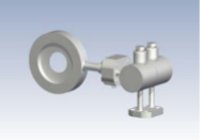
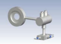
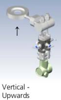
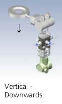
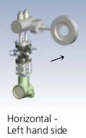
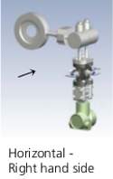
Installation Orientation
Technical Data
- Sizes : DN 40 - DN 400, 11⁄2" - 16", larger sizes on request
- Pressure rating : up to PN 40, 300 lbs, higher pressure ratings on request
- Temperature : Process : up to 400°C,
- Mounting style : Between flanges according to DIN or ANSI standards
- Flange facing : flat face (standard), raised face, DIN 2512 N, DIN 2513 R
- Overall length : 32 mm
- Material : Stainless steel AISI 316, others on request
- Design and calculation standards : ISO 5167, ASME MFC-3M.
- Vent or drain hole : On request
- β (d/D) : 0,5 and 0,6; other β on request.
- Accuracy : +/- 1.2 %
- Rangeability : 8:1
- Repeatability : better than 0,1 %
- Pressure loss : typical 150 mbar for liquid flow, and 50 mbar for gas flow (values are given at full flow)
- Reynolds No : Re > 5000
- Allowable differential pressure : max 2,5 bar
- Output signal : analogue 4 - 20 mA or Digital communication via protocol, HART, PROFIBUS, Fieldbus Foundation or others.
Local indicator (option): LCD showing flowing units or % - Power supply : 14 - 36 Vdc, typical 24 Vdc.
- Max load (24 Vdc) : 700 Ohm
- Enclosure : IP 67
Ex protection : intrinsically safe EEx ia IIC T6,Explosion proof EEx d IIC T6
Temperature : Ambient : -40 - +80°C
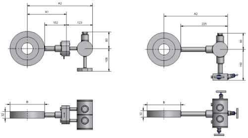
Sizes
DIN Flanges
| Size | Pipe OD | Pressure rating | Inner pipe diameter | ß = 0,5 Bore | ß = 0,6 Bore | B | A1 | A2 |
|---|---|---|---|---|---|---|---|---|
| DN 40 | 48,3 | PN 40 | 43,1 | 21,5 | 26,0 | 90 | 147 | 157 |
| DN 50 | 60,3 | PN 40 | 54,5 | 27,3 | 32,0 | 107 | 156 | 166 |
| DN 65 | 76,1 | PN 40 | 70,3 | 35,0 | 42,0 | 127 | 166 | 176 |
| DN 80 | 88,9 | PN 40 | 82,5 | 41,0 | 49,5 | 142 | 173 | 183 |
| DN 100 | 114,3 | PN 16 | 107,1 | 54,0 | 64,0 | 162 | 183 | 193 |
| DN 100 | 114,3 | PN 40 | 107,1 | 54,0 | 64,0 | 168 | 186 | 196 |
| DN 125 | 139,7 | PN 16 | 131,7 | 66,0 | 79,0 | 192 | 198 | 208 |
| DN 125 | 139,7 | PN 40 | 131,7 | 66,0 | 79,0 | 194 | 199 | 209 |
| DN 150 | 168,3 | PN 16 | 159,3 | 80,0 | 96,0 | 218 | 211 | 221 |
| DN 150 | 168,3 | PN 40 | 159,3 | 80,0 | 96,0 | 224 | 214 | 224 |
| DN 200 | 219,1 | PN 16 | 207,3 | 104,0 | 124,4 | 273 | 239 | 249 |
| DN 200 | 219,1 | PN 25 | 206,5 | 104,0 | 124,4 | 284 | 244 | 254 |
| DN 200 | 219,1 | PN 40 | 206,5 | 104,0 | 124,4 | 290 | 247 | 257 |
| DN 250 | 273 | PN 16 | 260,4 | 130,0 | 156,0 | 329 | 267 | 277 |
| DN 250 | 273 | PN 25 | 258,8 | 130,0 | 156,0 | 340 | 272 | 282 |
| DN 250 | 273 | PN 40 | 258,8 | 130,0 | 156,0 | 352 | 278 | 288 |
| DN 300 | 323,9 | PN 10 | 309,7 | 155,0 | 185,0 | 378 | 291 | 301 |
| DN 300 | 323,9 | PN 16 | 309,7 | 155,0 | 185,0 | 384 | 294 | 304 |
| DN 300 | 323,9 | PN 25 | 307,9 | 155,0 | 185,0 | 400 | 302 | 312 |
| DN 300 | 323,9 | PN 40 | 307,9 | 155,0 | 185,0 | 417 | 311 | 321 |
| DN 350 | 355,6 | PN 10 | 341,4 | 170,0 | 204,0 | 438 | 321 | 331 |
| DN 350 | 355,6 | PN 16 | 339,6 | 170,0 | 204,0 | 444 | 324 | 334 |
| DN 350 | 355,6 | PN 25 | 339,6 | 170,0 | 204,0 | 457 | 331 | 341 |
| DN 350 | 355,6 | PN 40 | 338,0 | 170,0 | 204,0 | 474 | 339 | 349 |
| DN 400 | 406,4 | PN 10 | 392,2 | 195,0 | 234,0 | 489 | 341 | 351 |
| DN 400 | 406,4 | PN 16 | 390,4 | 195,0 | 234,0 | 495 | 350 | 360 |
| DN 400 | 406,4 | PN 25 | 388,8 | 195,0 | 234,0 | 514 | 359 | 369 |
| DN 400 | 406,4 | PN 40 | 384,4 | 195,0 | 234,0 | 546 | 375 | 385 |
ANSI flanges
| Size | Pipe OD | Pressure rating | Sch. 10S Inner Pipe dia. | Sch. 40 Inner Pipe dia. | Sch. 80 Inner Pipe dia. | ß=05 Bore. | ß=06 Bore. | B | A1 | A2 |
| 1-1⁄2" | 48,3 | 150lbs | 42,7 | 40,9 | 37,3 | 20,0 | 24,0 | 85,7 | 145 | 155 |
| 300lbs | 95,3 | 150 | 160 | |||||||
| 2" | 60,3 | 150lbs | 54,7 | 52,5 | 49,3 | 26,0 | 31,5 | 104,8 | 154 | 164 |
| 300lbs | 111,1 | 158 | 168 | |||||||
| 3" | 88,9 | 150lbs | 82,8 | 77,9 | 73,7 | 39,0 | 47,0 | 136,5 | 170 | 180 |
| 300lbs | 149,1 | 177 | 187 | |||||||
| 4" | 114,3 | 150lbs | 108,2 | 102,3 | 97,2 | 51,0 | 61,0 | 174,6 | 189 | 199 |
| 300lbs | 181,1 | 193 | 203 | |||||||
| 6" | 168,3 | 150lbs | 161,5 | 154,1 | 146,3 | 77,0 | 92,5 | 222,3 | 213 | 223 |
| 300lbs | 279,4 | 242 | 252 | |||||||
| 8" | 219,1 | 150lbs | 211,5 | 202,7 | 193,7 | 101,0 | 121,6 | 279,4 | 242 | 252 |
| 300lbs | 308 | 256 | 266 | |||||||
| 10" | 273 | 150lbs | 264,6 | 254,5 | 242,8 | 127,0 | 153,0 | 339,7 | 272 | 282 |
| 300lbs | 362 | 283 | 293 | |||||||
| 12" | 323,9 | 150lbs | 314,7 | 303,2 | 289,1 | 150,0 | 180,0 | 409,6 | 307 | 317 |
| 300lbs | 422,3 | 313 | 323 | |||||||
| 14" | 355,6 | 150lbs | 346 | 333,3 | 317,5 | 165,0 | 198,0 | 450,9 | 327 | 337 |
| 300lbs | 485,8 | 345 | 355 | |||||||
| 16" | 406,4 | 150lbs | 396,8 | 381 | 363,6 | 190,0 | 228,0 | 514,4 | 359 | 369 |
| 300lbs | 539,8 | 372 | 382 |
Overall Dimensions
Installation Requirements
The Steemco flow meter can be mounted in a horizontal or vertical pipe. The condensing pot arrangement shall be mounted horizontally with the outlet pointing downwards. To insure high accuracy of measurement, long straight pipe runs up-stream from the flow meter is necessary. The required straight pipe run depends on the disturbance upstream. To maintain the 1.2% accuracy the minimum straight pipe run upstream shall be 14 x inner pipe diameter and 6 x downstream If an additional inaccuracy of 1⁄2 % is acceptable the required straight pipe runs are reduced to half of the above values. If mass flow is required for saturated steam, ask for a multivariabe transmitter. If mass flow is required for superheated steam, ask for STEEMCO-MAS and multivariabe transmitter.
Steemco Coding
| 1. Type | |
|---|---|
| In AISI 316 with transmitter flange | code ST1 |
| integrated manifold | code ST2 |
| Integrated condensing chamber | code ST3 |
| 2. Size | |
| DN 40 DIN standard | code 040 |
| DN 50 DIN standard | code 050 |
| DN 65 DIN standard | code 065 |
| DN 80 DIN standard | code 080 |
| DN 100 DIN standard | code 100 |
| DN 125 DIN standard | code 125 |
| DN 150 DIN standard | code 150 |
| DN 200 DIN standard | code 200 |
| DN 250 DIN standard | code 250 |
| DN 300 DIN standard | code 300 |
| DN 350 DIN standard | code 350 |
| DN 400 DIN standard | code 400 |
| 11⁄2” ANSI standard | code 01.5 |
| 2” ANSI standard | code 002 |
| 3” ANSI standard | code 003 |
| 4” ANSI standard | code 004 |
| 6” ANSI standard | code 006 |
| 8” ANSI standard | code 008 |
| 10” ANSI standard | code 010 |
| 12” ANSI standard | code 012 |
| 14” ANSI standard | code 014 |
| 16” ANSI standard | code 016 |
| 3. Pressure rating | |
| PN 10 DIN standard | code 10 |
| PN 16 DIN standard | code 16 |
| PN 25 DIN standard | code 25 |
| PN 40 DIN standard | code 40 |
| 150 lbs ANSI standard | code 15 |
| 300 lbs ANSI standard | code 30 |
| 4. Facing | |
| DIN 2526 Form A | code 26 |
| DIN 2513 Form R13 | code 13 |
| DIN 2512 Form N | code 12 |
| Raised face RF ANSI standard | code RF |
| Flat face FF ANSI standard | code FF |
| 5. Pipe schedule ( only applicable for ANSI flanges) | |
| DIN flanges | code 00 |
| Schedule 10S | code 10 |
| Schedule 40 | code 40 |
| Schedule 80 | code 80 |
| 6. β value | |
| β value 0.5 | code 5 |
| β value 0.6 | code 6 |
| β value free choice | code 9 |
| 7. Drain/vent hole Ø3 mm | |
| Without drain/vent hole | code 0 |
| With drain/vent hole | code 1 |
| 8. manifold valve | |
| ST1 - Without | code 0 |
| ST1 - 3 valve manifold | code 1 |
| ST2 - Integrated manifold | code 2 |
| ST3 - Integrated condensing chamber without manifold | code 3 |
| ST3 - integrated condensing chamber with manifold | code 4 |
| 9. Mounting Position | |
| Horizontal pipe right hand | code HR |
| Horizontal pipe left hand | code HL |
| Vertical pipe down | code VD |
| vertical pipe up | code VH |
| 10. Differential pressure transmitter | |
| Without | code 0 |
| Included code Original transmitter type no. |
Examples
DN 100 STEEMCO ST1 in stainless steel PN 40 with DIN2526 facing, β value 0,6, with drain hole, for horizontal right hand mounting and 3 valve double flanged manifold valve type G3H and without transmitter has following code:
ST1-100-40-26-00-6-1-1-HR-0
8" STEEMCO ST2 in stainless steel 150 lbs with RF facing, β value 0,5, without drain hole, with Integrated manifold, for vertical mounting flow direction downwards has following code:
ST2-008-15-RF-40-5-0-2-VD-0
Works with:-
Differential pressure transmitters:-IDP10; IDP15; IDP25; IDP31; IDP50
And all our Absolute Pressure and Gauge Pressure transmitters, Temperature sensors and mass flow computers.
MultiVariable Transmitters :- IMV25, IMV30
If you require further information on this product or would like a quotation, please contact dp-flow on:
email: sales@dp-flow.co.uk
sales +44(0)1608 544222
Supplied by DP-Flow