Model IFOU Integral flow Orifice Assembly IFOU
This integral orifice assembly is used in combination with pneumatic or electronic d/p Cell Transmitter to accurately measure low flow rates of liquids or gases.
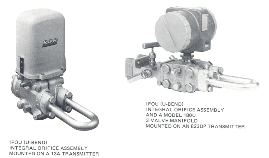
The IFOU Integral Flow Orifice Assembly (U-bend type) is used with a pneumatic or electronic differential pressure transmitter. This combination uses the differential pressure created by the orifice to measure extremely low rates of process flow.
Features
- Design that virtually eliminates cavities and dead-end areas. Flow is through transmitter body.
- Can handle clean or dirty fluids.
- Ideal design for liquids which may precipitate solids, congeal, or polymerize, and for vapors that tend to condense.
- Both process connections are made to same end of transmitter body.
- No separate piping required for transmitter impulse lines.
- Upstream straight run of pipe not required.
- Can be installed horizontally or vertically.
CONVENIENT SIZING
The IFOU Integral Flow Orifice Assembly is suitable for liquid and gas applications. By choosing the correct orifice bore, almost any desired low flow rate can be measured.
Using flow data supplied by the user at the time the order is placed for the orifice assembly and the d/p Cell transmitter, we will supply a flow calculation specification data sheet with orifice assembly.
This data sheet lists complete transmitter-orifice assembly flow data for the user's process.
CAN BE USED WITH MANY TRANSMITTERS
The IFOU Integral Flow Orifice Assembly can be used with the following d/p Cell transmitters;
15A, 13A, E13DL, E13DM, 823DP, IDP10, IDP10S AND IMV30 Series, static pressure Code 3.
HANDLES WIDE RANGE OF LOW FLOW RATES
The orifice is available with a choice of six standard bore diameters (see Physical Specifications). In addition, any bore diameter between 0.381 and 6.350mm (0.015 and 0.250 in) can be supplied as an option.
Selecting among the six standard orifices, water flows as low as 0.020 L/min (0.005 U.S. gpm) and as high as 60 L/min (15 U.S. gpm) at standard conditions can be measured and air flows as low as 0.03 m3/h (0.02 ft3/min) and as high as 50m3/h (30ft3/min) at standard conditions can be measured).
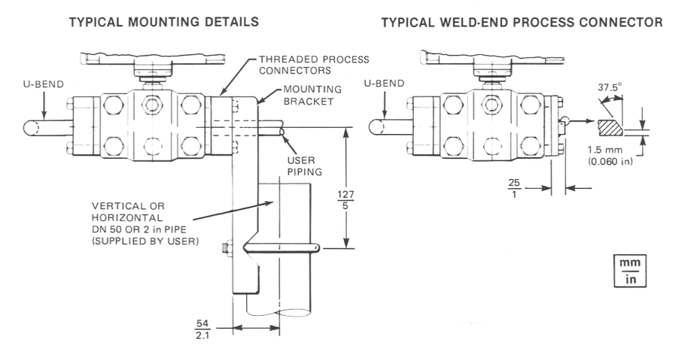
SIMPLIFIED INSTALLATION
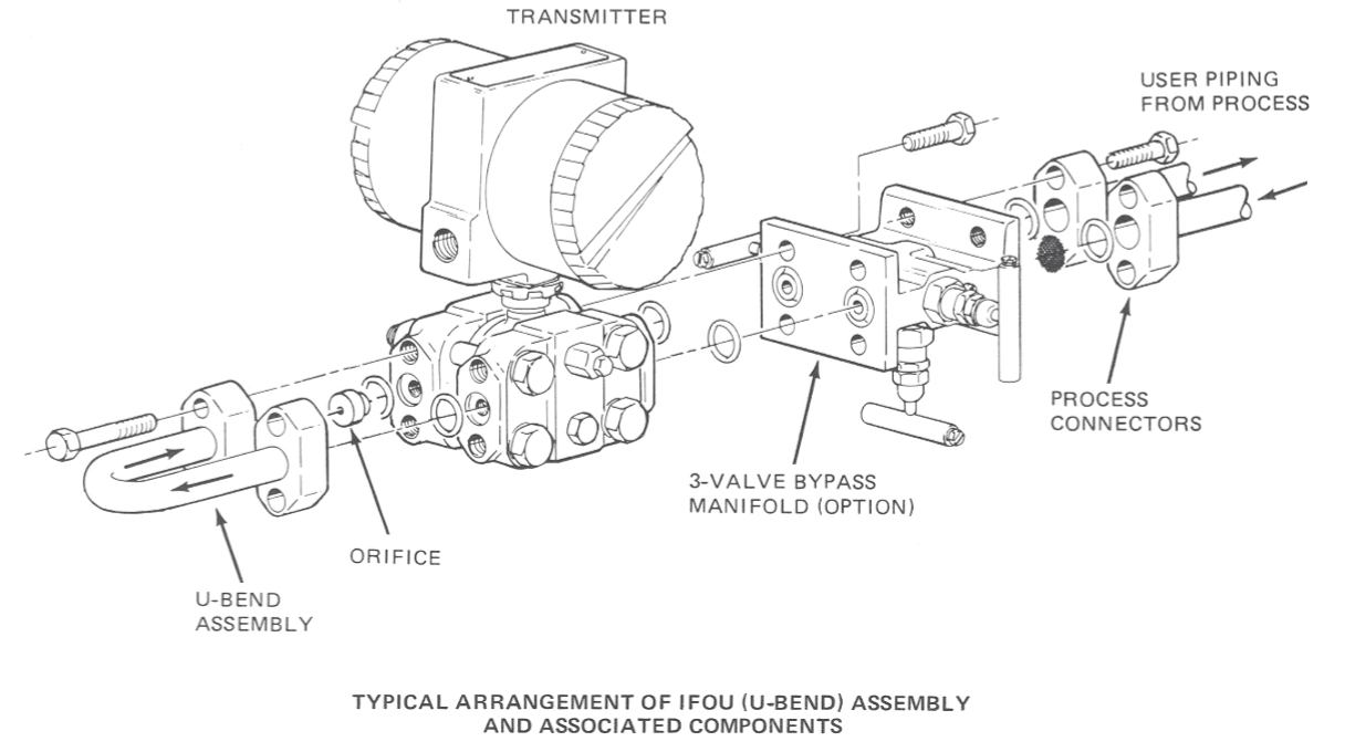
Since the U-bend assembly is installed directly onto the transmitter, and since the transmitter is connected to the process line, the orifice assembly and transmitter become part of the piping.
The design of the assembly allows the user of a close-mounted Model 180U three-valve manifold. With this manifold the d/p Cell transmitter can be rezeroed, the orifice can be cleaned or replaced, or the transmitter can be removed from service, without shutting down the process.
STANDARD SPECIFICATIONS
Static Pressure Rating Up to 20.7 MPa (3000 psi, or 207 bar or kg/cm2), or static pressure rating of associated transmitter; whichever is less. For pressure rating of transmitter, see applicable transmitter specifications.
Process Connections See applicable transmitter specifications. (Note the minimum size is 1/2 NPT or R 1/2.)
Pressure Loss 100% of measured differential.
Temperature Limits Temperature limits of associated transmitter. See applicable transmitter specifications.
Orifice Flow Coefficient Uncertainty±3% for standard orifice-bore diameters and orifice-bore Reynolds numbers (Rd) as low as 1000. Coefficient uncertainty can be reduced by tflow calibrating the system (orifice assembly and transmitter).
Transmitter Accuracy Refer to specifications of associated transmitter.
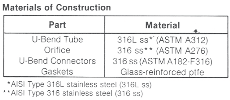
Physical Specifications
Standard Orifice Bore Diameters 0.508, 0.864, 1.511, 2.527, 4.039 and 6.350 mm (0.0200, 0.0340, 0.0595, 0.0995, 0.1590, and 0.02500 in). Note that orifice bore diameters larger than 4.039 mm (0.1590 in) are not recommended for use with 823DP Transmitter.
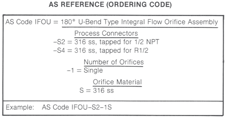
Ordering Instructions
- Specify AS Reference
- SPecify Orifice Bore Size or Provide Complete Flow Data if weare to Calculate.
- Optional 3-Valve Manifold (Model 180U)
- User Tag Data (Identification Number)
Dimensions --- Nominal
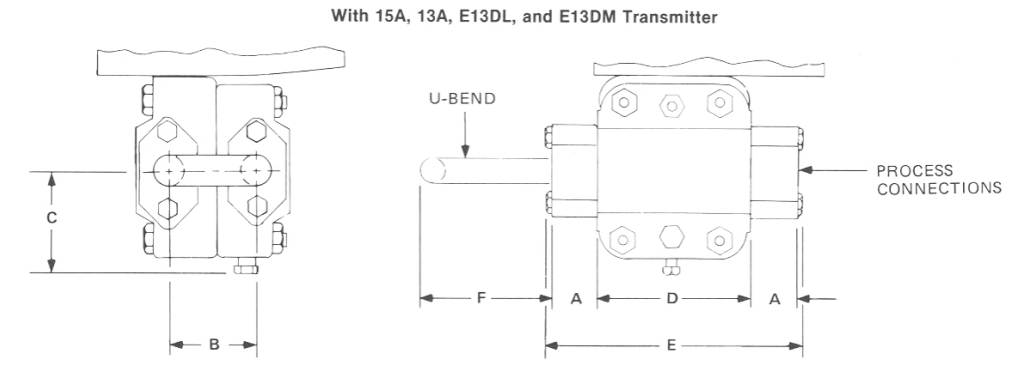
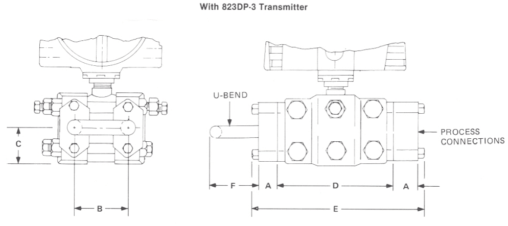
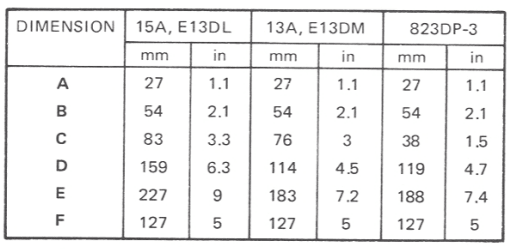
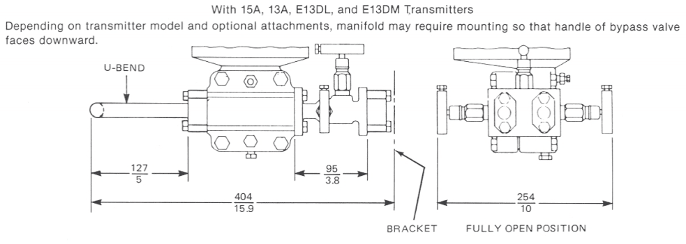
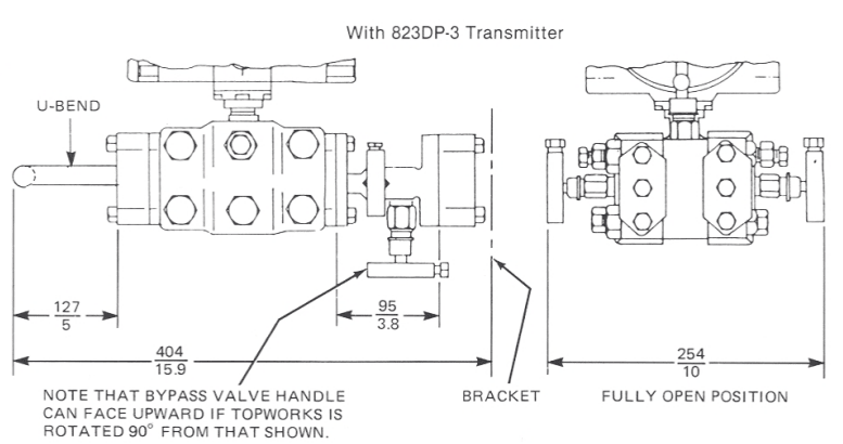
Transmitters Equipped with Model 180U 3-Valve Manifold