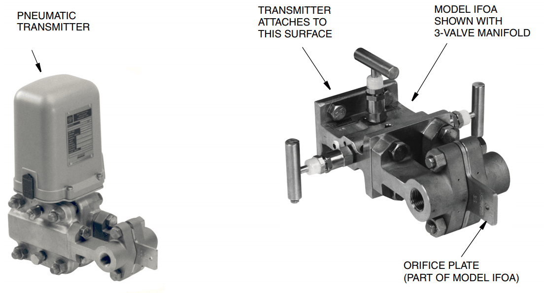
The Model IFOA Integral Flow Orifice Assembly is used in combination with an electronic or Pneumatic d/p Cell Transmitter to accurately measure liquid, gas, or steam flow in 1/2 in, 1 in, and 1 1/2 in (approximately DN 15, DN 25, and DN 40) size pipes.
The Model IFOA Integral Orifice Assembly in combination with a d/p Cell Transmitter uses the differential pressure created by the orifice to measure, with high accuracy, process flows in 1/2 in, 1 in, and 1 1/2 in size pipes.
This integral flow orifice assembly features:
- Very high accuracy when equipped with associated piping.
- Process-wetted materials available for use with both corrosive and noncorrosive fluids.
- Various process pipe end connections available
- Can be used with any differential pressure transmitter having standard process connections. The transmitter can be either integrally coupled or remotely connected.
- A 3-Valve Manifold is recommended for mounting between the Model IFOA and transmitter.
- Process-wetted material meets NACE Standard MR-01-75.
- Self-centering orifice plate design.
- No-flow-through transmitter body.
- Orifice plate manufacture consistent with ASME, ISO, and AGA-3 standards
CONVENIENT SIZING
The Model IFOA is suitable for liquid, gas, and steam applications. By choosing the correct combination of assembly size and orifice bore, almost any desired flow rate, with either turbulent or laminar flow conditions, can be measured.
Using flow data supplied by the user at the time the order is placed for the Model IFOA and the transmitter, IPS supplies a flow calculation and specification sheet with the orifice assembly.
This sheet lists complete transmitter-orifice assembly flow data for the user’s process.
HANDLES WIDE RANGES OF FLOW RATES
The flow rate ranges handled by these integral orifice flow assemblies (each range depends on the specific combination of assembly size and orifice bore) are those frequently found in chemical and petrochemical plants, research projects, and high-accuracy metering applications.
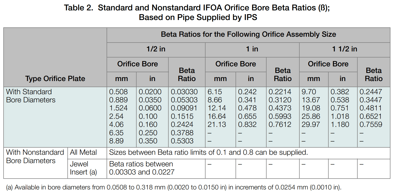
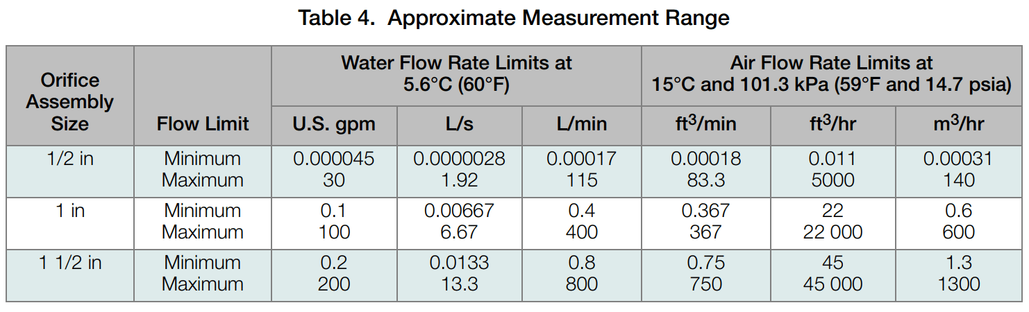
In addition, the very low flow rates that the 1/2 in size can measure can be further extended by using an orifice plate with a jewel insert. This insert can have an orifice diameter as small as 0.0508 mm (0.0020 in) and permits measurement of extremely low flow rates. The approximate measurement range of each orifice assembly size is listed in Table 4.
HIGHLY ACCURATE MEASUREMENTS
The orifice assembly can be supplied with associated piping welded to it. This piping can have a variety of end connections (for installation into the user’s process piping). All essential parts are bored to assure a precise inside diameter which is highly concentric with the orifice bore. This permits a Beta ratio (ratio of orifice bore to pipe ID) that is tightly controlled. The results are measurements that are far more accurate than could otherwise be obtained.
AVAILABLE IN A VARIETY OF MATERIALS, SIZES, AND CONFIGURATIONS
The orifice plate and body assembly are available in several metals to meet the requirements of almost any process, including NACE material standards. (Only AISI Type 316 stainless steel [316 ss] construction is available when the orifice assembly is supplied with associated piping.) The assembly is available in 1/2 in, 1 in, or 1 1/2 in pipe sizes. The process piping can be either screwed or welded to the body.
Several standard orifice bore diameters are available for each assembly size. In addition, non-standard bore sizes, between Beta ratio limits of 0.1 and 0.8, can be supplied. See Table 2.
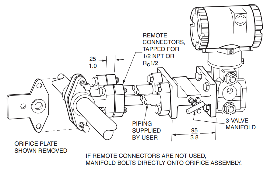
REMOTE CONNECTORS
If the temperature of the process fluid exceeds the temperature limit of the transmitter (so that the transmitter must be mounted away from the orifice assembly), or, if for other reasons, it is desirable to locate the transmitter elsewhere, optional connectors are available for remote-mounting the transmitter
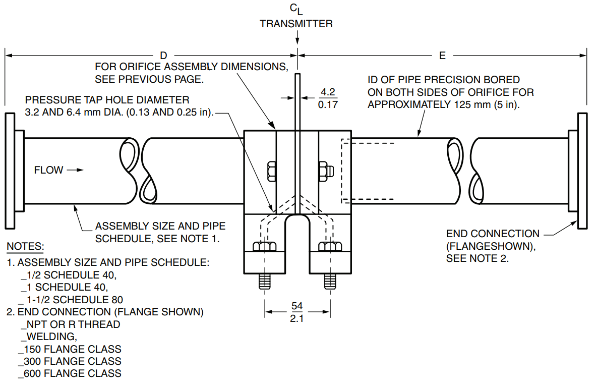
SIMPLIFIED INSTALLATION
The orifice assembly becomes part of the process piping. The transmitter is bolted directly onto the orifice assembly; thus, no transmitter piping is required.
The transmitter can be isolated or bypassed by the addition of a three-valve bypass manifold. This permits the zeroing, calibration check, and maintenance of the transmitter without either interrupting the flow or removing the integral orifice assembly from the process line. Both the bypass manifold and the transmitter are bolted together as a unit, and the pair is mounted directly onto the orifice assembly. Refer to PSS 2B-1Z2 A for a listing of manifolds offered.
FUNCTIONAL SPECIFICATIONS
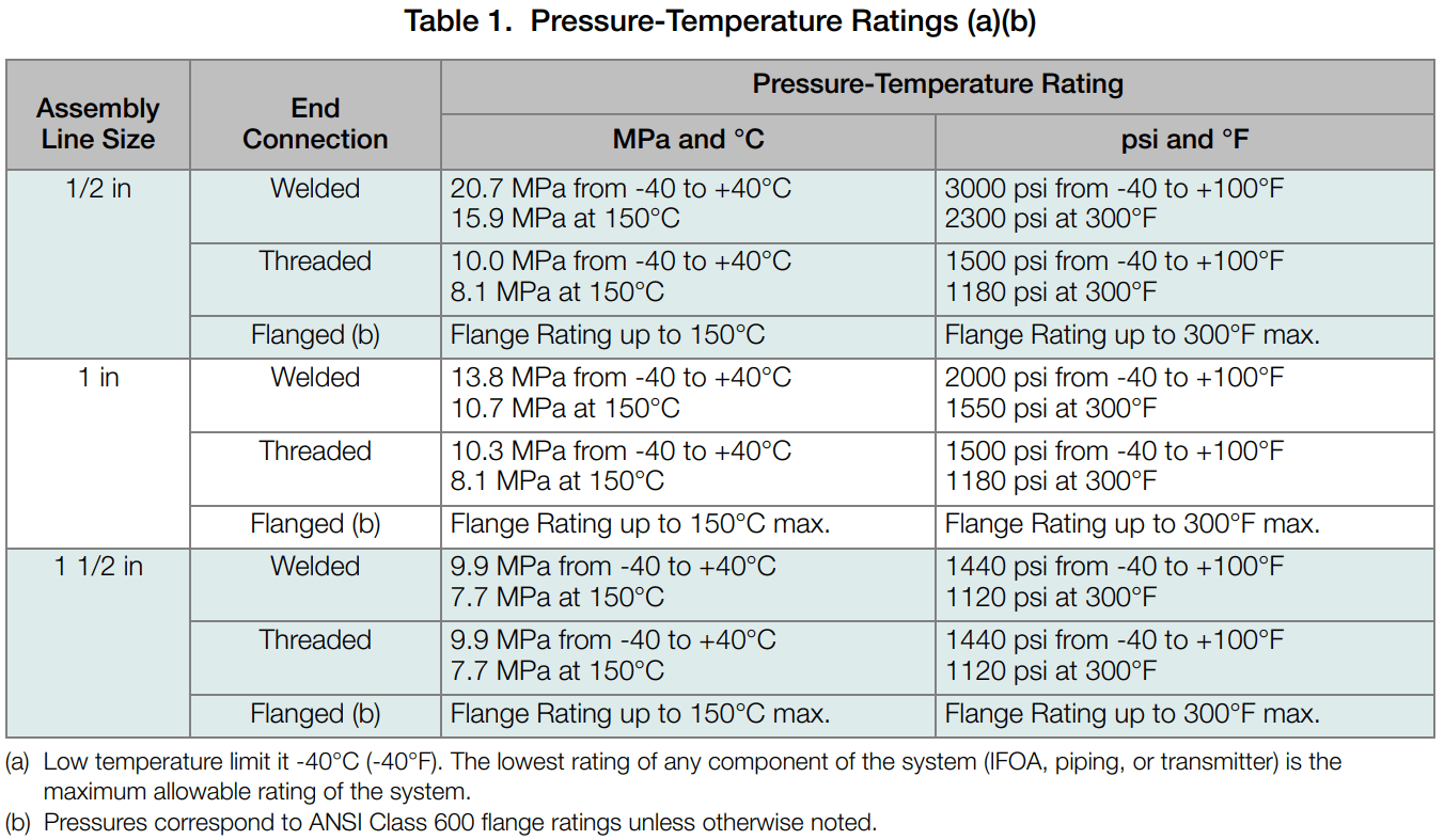
Pressure-Temperature Ratings
Refer to Table 1.
Remote Pressure Connectors
If the process temperature is higher than the temperature rating of the transmitter, remote connectors (see Model Code section) are available to mount transmitter away from orifice assembly. However, the temperature of transmitter must not exceed its rating. The remote connectors are provided with the necessary bolts and gaskets. Two sets are required: one set is provided with the orifice assembly and one set with the transmitter. Connecting piping is supplied by the user
Mounting
The orifice assembly is inserted into the user’s process line and becomes a permanent part of the piping. The transmitter bolts onto the orifice assembly body. If optional remote connectors are used, the transmitter can be located away from the orifice assembly.
Pressure Taps
Corner
Orifice Inlet Edge
BORE DIAMETER UP TO 1.5 mm (0.06 in)
Quadrant edge
BORE DIAMETER ABOVE 1.5 mm (0.06 in)
Square edge
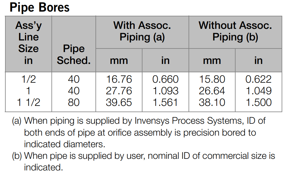
Pipe Bores
Orifice Bores
Refer to Table 2.
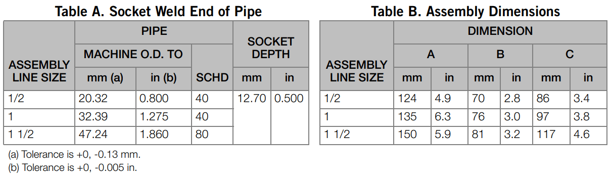
Process End Connections
ASSEMBLY WITHOUT ASSOCIATED PIPING
Body connections for 1/2 in, 1 in, or 1 1/2 in pipe; NPT or Rc pipe tap, or prepared for socket welding, as specified.
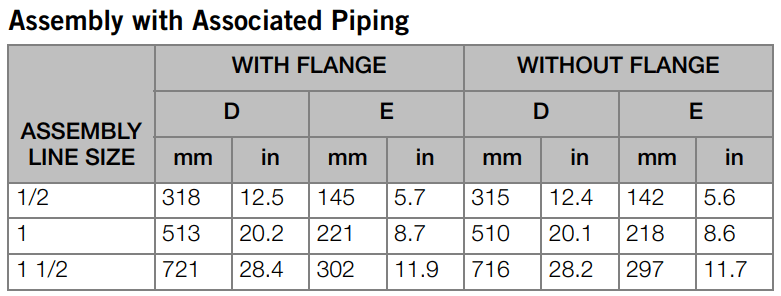
ASSEMBLY WITH ASSOCIATED PIPING
1/2 in, 1 in, or 1 1/2 in pipe is welded to body; outer ends are either threaded (NPT or R), prepared for welding, or flanged (ANSI; Class 150, 300, or 600), as specified. Pipe lengths are approximately 18 pipe diameters upstream and 7 pipe diameters downstream.
PERFORMANCE SPECIFICATIONS
(Refer to associated transmitter specifications for transmitter accuracy)
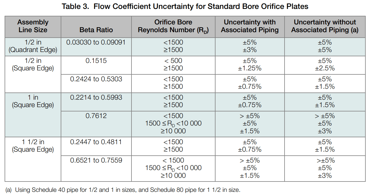
Flow Coefficient Uncertainty
Table 3 lists flow coefficient uncertainties at various orifice bore Reynolds Numbers when using standard bore orifice plates. The flow coefficient uncertainty can be reduced by a laboratory flow calibration of the orifice assembly. Refer to IPS for details.
Measurement Range
See Table 4 and also refer to FlowExpertPro.
PHYSICAL SPECIFICATIONS
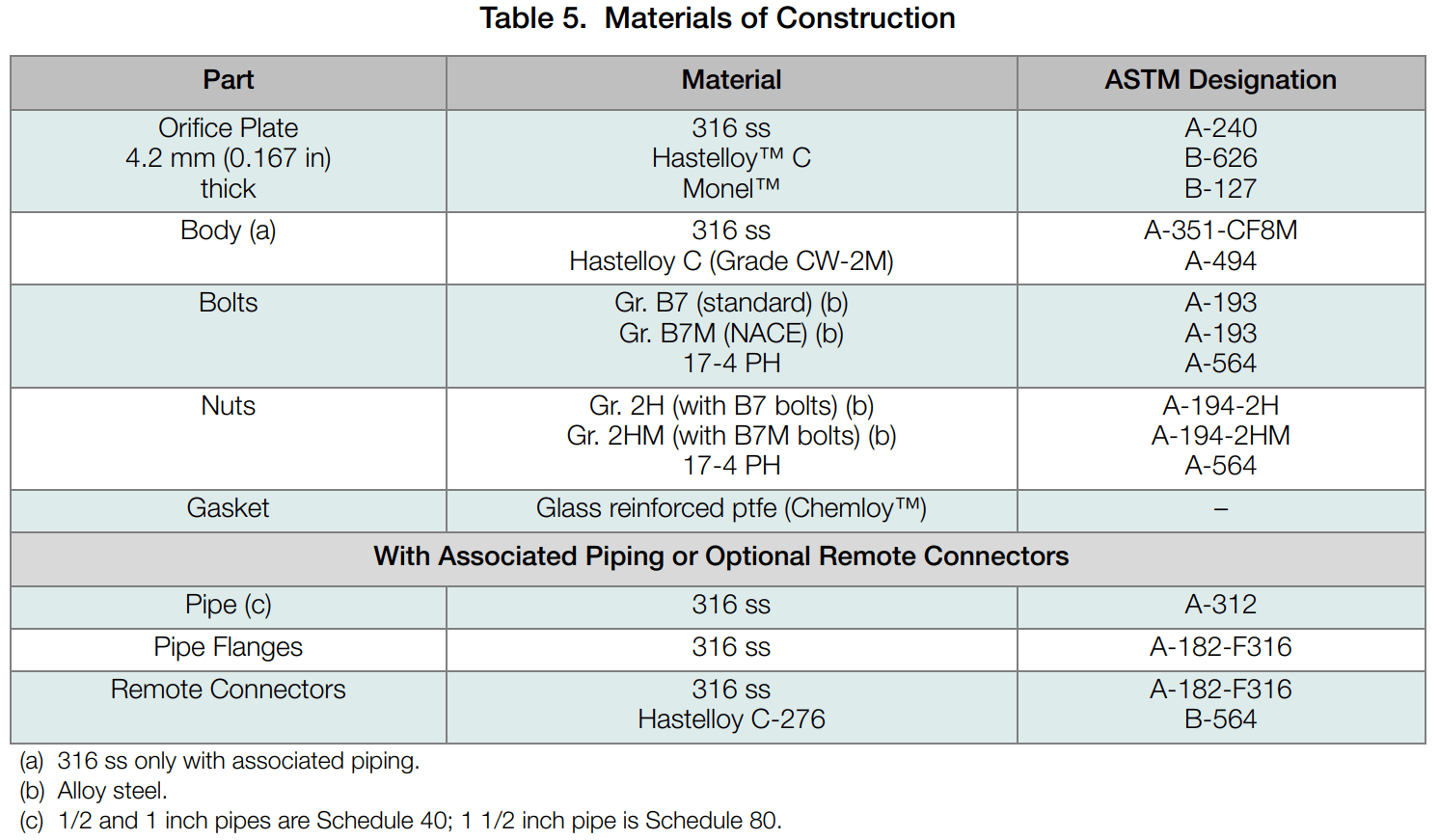
Material of Construction
See Table 5.
Orifice Plate Identification
One side of the handle has “INLET” and the plate material stamped on it; the other side has the part number and bore diameter
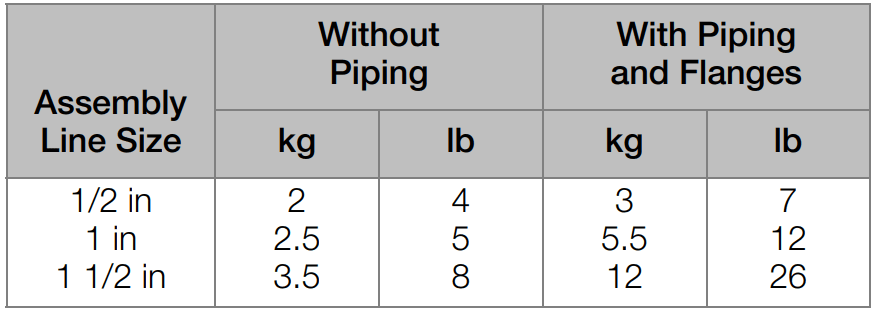
Approximate Mass
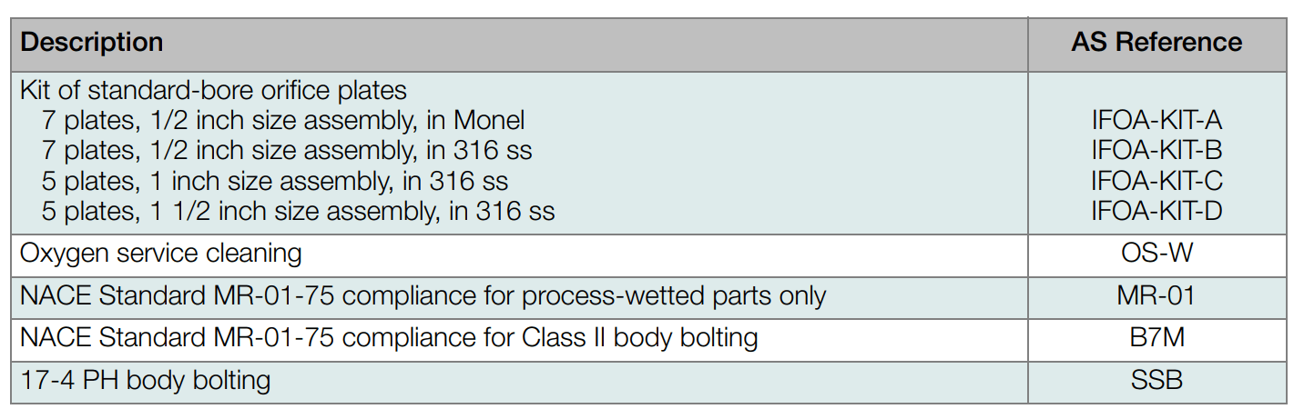
Optional Specifications
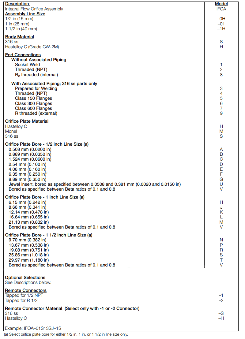
Model Code
DIMENSIONS - NOMINAL
mm
----
in
ASSEMBLY WITHOUT ASSOCIATED PIPING
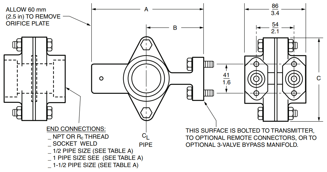
ASSEMBLY WITH ASSOCIATED PIPING
Assembly with Associated Piping
mm
----
in
ASSEMBLY WITH OPTIONAL REMOTE CONNECTORS AND A 3- VALVE BYPASS MANIFOLD