Model IFO Integral Flow Orifice In-Line IFO
This in-line type integral flow orifice is used in combination with a pneumatic or electronic d/p Cell Transmitter to accurately measure very low flow rates of liquids or gases. Static pressure ratings up to 40 MPa (6000 psi) can be accommodated.
USED WITH MANY TRANSMITTERS
The Model IFO can be used with the following d/p Cell transmitters: 13A, 13H, and 15A Series Pneumatic Transmitters, and E13DL, E13DM, E13H, 823DP-3, IDP10, IDP10S and IMV30 Series Electronic Transmitters.
SIMPLIFIED INSTALLATION
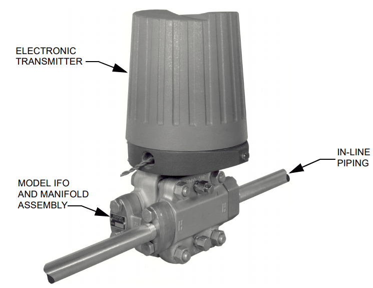
Since the IFO assembly is installed directly onto the transmitter, and since the transmitter is connected to the process line, the orifice assembly and transmitter become part of the piping
INTEGRAL STRAIGHT-THROUGH DESIGN
The Model IFO is an in-line type orifice assembly that is integrally mounted to pneumatic or electronic d/p Cell Transmitters. The measured fluid passes through the high pressure side of the transmitter and orifice only (not the low pressure side). No separate piping is required for instrument impulse leads, and an upstream straight line of pipe is also not required.
HANDLES WIDE RANGE OF LOW FLOW RATES
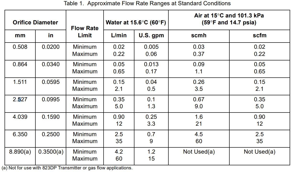
The orifice is available with a choice of seven standard bore diameters (see Physical Specifications section). In addition, any bore diameter between 0.508 and 6.350 mm (0.020 and 0.250 in) can be supplied as an option.
Selecting among the seven standard orifices, water flows as low as 0.020 L/min (0.005 U.S. gpm) and as high as 60 L/min (15 U.S. gpm) at standard conditions can be measured; and air flows as low as 0.03 m 3/h (0.02 ft 3/min) and as high as 60 m 3/h (35 ft 3/min) at standard conditions can be measured. In addition, lower flow rates than those listed can be achieved by adding an optional jewel insert to the orifice. The jewel insert can have an orifice diameter as small as 0.0508 mm (0.0020 in) and permits the measurement of extremely low flow rates.
CONVENIENT SIZING
The Model IFO is suitable for liquid and gas applications. By choosing the correct orifice bore, almost any desired low flow rate within the stated flow rate limits can be measured. Using flow data supplied by the user at the time the order is placed for the orifice assembly and the d/p Cell transmitter, will supply a flow calculation-specification data sheet with the orifice assembly.
This data sheet lists complete transmitter-orifice assembly flow data for the user’s process.
FUNCTIONAL SPECIFICATIONS
Static Pressure Rating
Static pressure rating is 40 MPa (6000 psi), or up to the static pressure rating of the d/p Cell Transmitter, whichever is less.
Process Connections
Tapped for 1/2 NPT
Pressure Loss
100% of the measured differential pressure.
Standard Orifice Diameters
0.508, 0.864, 1.511, 2.527, 4.039, 6.350, or 8.890 mm (0.0200, 0.0340, 0.0595, 0.0995, 0.1590, 0.2500, or 0.3500 in). The 8.890 mm (0.3500 in) orifice diameter is not used with the 823DP Transmitter, or in gas flow applications.
Flow Rate Ranges
See Table 1.
PERFORMANCE SPECIFICATIONS
Orifice Coefficient Tolerance
±3.0% for standard orifice bore sizes and Reynolds Numbers as low as 1000. Coefficient of uncertainty may be reduced by flow calibration of the entire assembly including the orifice, manifold, and d/p Cell Transmitter.
Transmitter Accuracy
Refer to applicable Transmitter Product Specification Sheet (PSS).
PHYSICAL SPECIFICATIONS
Materials of Construction
MANIFOLD AND INLET CONNECTION AISI Type 316 stainless steel (316 ss) ORIFICE 316 ss, Monel, or Hastelloy C.
GASKETS
Glass reinforced ptfe
Threaded End Connections
Tapped for either R 1/2 or 1/2 NPT, as specified
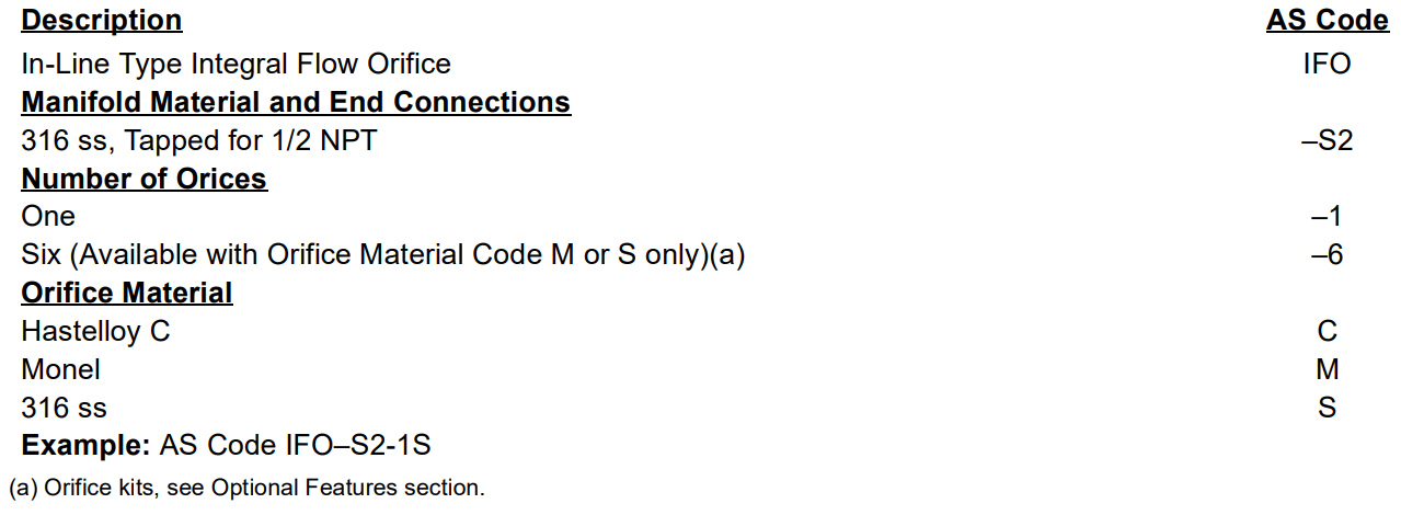
AS REFERENCE CODE (ORDERING CODE)
OPTIONAL FEATURES
Special Orifice Bores
Any bore between 0.381 and 6.350 mm (0.0150 and 0.2500 in) can be provided. To order, specify material and bore, or provide complete flow data.
Orifice Kit
A kit of six standard bore orifices in 316 ss or Monel is available.This kit may be ordered by specifying "-6" in the Number of Orifices section of the AS Reference Code.
Jeweled Orifice
Jeweled center synthetic sapphire orifices mounted in 316 ss holders are available in any bore size between 0.0508 and 0.381 mm (0.0020 and 0.0150 in) in 0.0254 mm (0.0010 in) increments.These can be used for upper rangevalue flow rates as low as 10 cm 3/h (5 x 10 -5 U.S. gpm) of water at standard conditions and 340 cm 3/h (2 x 10 -4 ft 3/min) of air at standard conditions. To order, substitute "J" for Orifice Material in the AS Reference Code and specify bore, or provide complete flow data.
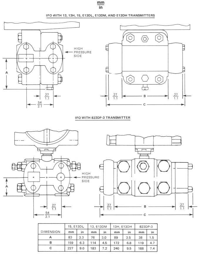
DIMENSIONS—NOMINAL
ORDERING INSTRUCTIONS
- Specify AS Reference Code
- Specify Orifice Bore Diameter, or Provide Complete Flow Data.
- Optional Features
- User Tag Data