7000-Threaded; 8000 -Wafer
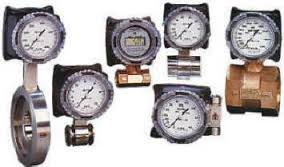
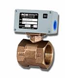
The RCM Flo-Gage is a direct reading flow meter with a large, easy to read dial calibrated in engineering units (GPM, SCFM, l/m, etc.). The Flo-Gage measures flow based on a pressure differential created across a built-in calibrated nozzle. The meter is self-contained and complete. It does not require external power connections, separate orifices, or blocking, purging or equalizing valves.
The Flo-Gage is suitable for measuring water, oil and most other low viscosity liquids which do not deposit out and which are compatible with the materials of construction. The Flo-Gage is also suitable for measuring compressed air, oxygen, carbon dioxide and many other non-toxic compressed gases. (Specify Option I). Saturated steam can also be measured up to 120 psig. (Option K).
The Flo-Gage can be fitted with a transmitter with current or frequency outputs for remote indication or totalization, or with reed switch contacts for signaling high or low flows.
Typical Applications
The Flo-Gage flowmeter has been developed for industrial applications where durability and reliability are important considerations in the monitoring of flow. The Flo-Gage has accuracy for most industrial processes and is particularly suited for applications where compactness, low cost, minimal maintenance and resistance to accidental damage are important factors.
Typical applications include: lube oil monitoring, blending processes, cooling water, reverse osmosis systems and compressed air measurement.
The RCM Flo-Gage flow meter features are:
- Sturdy, in-line, metal construction to withstand piping stresses
- Dial won’t crack, glaze or become hard to read
- Expanded analog 270o dial for reading at a glance
- Large 3.5” (90mm) dial
- Suitable for use with both opaque and clear fluids
- Measures 6:1 range with ±3% F.S. accuracy
- Dial and case factory configured for quick installation–but easily field reconfigured if needed
Slurries and Suspended Solids
Liquids with finely dispersed solids in suspension can be metered successfully provided:
- Liquids with finely dispersed solids in suspension can be metered successfully provided:
- A) Solids content is low enough to permit line fluids to behave as a low viscosity liquid.
- B) Specific gravity effects are accounted for.
- C) Solids do not plug up the pressure ports.
- D) Abrasive action does not erode meter nozzle.
SERVICES NOT RECOMMENDED
Flo-Gages are not recommended for the following kinds of services:
- A) Resins, paints or monomers which can form solid deposits in the piping system.
- B) “Super-solvents” which attack most available elastomer O-ring seals.
- C) Sulfuric acid in any concentration.
- D) Foams which tend to have inconsistent densities.
- E) Foods and pharmaceuticals which require crevice free construction for clean-in-place sterilization.
- F) Toxic substances requiring hermetically sealed enclosures.
- G) Viscous fluids (more than 500 centipoises) which affect meter accuracy at low flow rates.
- H) Pumping systems using piston pumps which produce non-steady flow conditions.
- I) Gravity-fed systems having less head than the pressure loss across the meter at normal operating conditions.
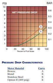
PRESSURE DROP CHARACTERISTICS
COOLING SYSTEMS FOR MACHINERY
- Monitor correct cooling flow to machinery. Protect valuable equipment by using a low flow switch to shut down machinery before damage.
- The Flo-Gage will not foul with small debris frequently found in cooling systems. Fouling can cause typical flow switches to stick and fail to detect low flow conditions.
MONITOR LUBRICATION OIL TO TURBINES AND OTHER EXPENSIVE EQUIPMENT
- Flo-Gages are ideal for measuring lube-oil. They do not require that the oil be transparent to be measured. Low flow switches can add additional protection.
PROCESS CONTROL
Use a Flo-Gage to measure the optimum flow rate for cooling water under various load conditions. The Flo-Gage can then be used to quickly set the most economical flow rate.
MONITOR CUTTING OIL FLOW IN AUTOMATIC PROCESS HEAT EXCHANGER MACHINING CENTERS
Proper flow of cutting oil is essential to machining operations. Automatic machines which run unattended require monitoring of the flow of cutting fluids. The gage allows quick setting of the proper flow rate. The low flow switch can stop machines before bad parts are produced.
COMPRESSED AIR MONITORING FOR ENERGY CONSERVATION
Mount a Flo-Gage downstream of a pressure regulator to monitor compressor operation and air utilization. Flo-Gages can be used at the compressor as well as at key distribution points. Reduction in wasted air can pay back installation cost in as little as a few weeks.
Selecting the Flo-Gage is easy...and our factory staff are always glad to help!
Select a) body size, b) mounting method, c)body material, d) direction of flow, e) full
scale flow rate, f) options (if required) and service, select option I and specify g) switches (if required).
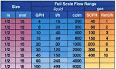
- A) BODY SIZE - pipe size at the meter inlet. Select from Standard Flow Rates and Body Sizes.
- B) SERIES (mounting method)
- 7 - threaded units provided with FNPT connections standard.
- (FBSP parallel threads available on request for bronze and monel meters.)
- 8 - wafer units mount between any standard 150 or 300 class flanges (or international equivalent).
- C) MATERIAL -
- 1 = Bronze
- 2 = Monel
- 3 = Stainless steel (316)
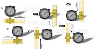
- D) FLOW DIRECTION – Select L, R, VUL, VUR, VDL, VDR (see diagram)
- E) FLOW RATE (full scale) - Select from Standard Flow Rates and Body Sizes. Prefix full scale with “M” for metric units.
- F) OPTIONS (if required) - Select from table of Options. Note: For gas service, select option I and specify gas being measured, inlet temperature and pressure.
- G) SWITCHES (if required)
- 1S2 - One single pole double throw switche
- 2S2 - Two single pole double throw switches
- EXAMPLE: 3/4-71-R-20-AD-1S2 is the catalog number for a 3/4” NPT Series 7000 Flo-Gage of bronze construction, flow direction from left to right, flow range of 20 GPM full scale, equipped with optional seals of Viton, optional gasketed case and one single-pole double throw reed switch.
AVAILABLE OPTIONS
- OPTIONS A & B: O-RING SEALS.
- Viton* (option A), EPR (option B) or Teflon* (PTFE) (option B2) O-rings may be supplied in lieu of the standard Buna-N O-ring. See table of “Recommended Meter Materials” for suggested materials.
- OPTION C: CALIBRATION FOR SPECIFIC GRAVITY OPTION
- All Flo-Gages are normally calibrated for water with a specific gravity of 1.0 (density of 62.4 lbs. ft.3). This option provides a custom sized orifice to accommodate the actual specific gravity of the measured liquid.
- OPTION D: GASKETED METER HOUSING
- If the meter is to be exposed to the weather, marine service, splashing liquids, corrosive vapors, or extreme humidity or dusty conditions, then a gasketed meter housing is recommended. Gaskets are installed at the body flange, back cover plate and under the dial crys tal to make the housing leaktight.
- OPTION E: NON-STANDARD FLOW RATES. Various fullscale flow rates are available for each pipe size as indicated in the charts of “Standard Flow Rates and Body Sizes”. Special orifices can be furnished for smaller flows. Consult factory if this option is desired.
- OPTION ES: LOW FLOW RATES
- A low flow meter is available with 1/2” female NPT connections for measuring the flow of liquids as low as 1 GPH and gases as low as 10 SCFH.
- G: CUSTOM SCALES AND DIALS
- Non-standard flow rates and custom dial patterns require preparation of special artwork. A one-time charge is made for each custom dial pattern or non-standard scale.
- OPTION H: 400 PSIG SERVICE
- Meters equipped with bellows made of Inconel 718** are available with service ratings to 400 psig and may be used where service conditions permit use of stainless steel. A slight increase in pressure drop across the meter results when these bellows are used.
- OPTION I: COMPRESSED GAS SERVICE.
- Meters intended for compressed gas service require individual sizing of meter orifices to suit the desired flow rate, gas composition, line pressure and temperature. Dials are marked with type of gas, specific gravity, line pressure and temperature.
- OPTION J: PEAK FLOW INDICATOR.
- A second pointer is provided with a reset knob to provide an indication of the maximum flow rate achieved since reset.
- OPTION K: SATURATED STEAM SERVICE.
- The steam service option includes EPR seals, SS bellows and an inverted aluminum housing. Steam pressures are limited to 120# saturated unless remote mounted (Option R2 and R3).
- OPTION N: AMMONIA SERVICE.
- This option includes brass free construction throughout, EPR seals, a stainless gear movement and gasketed case. Price includes calibration for specific gravity, pressure and temperature. This option available for stainless steel models only.
- OPTION P: PANEL MOUNT.
- The meter may be mounted behind a panel for pipe sizes 1 1/2” and smaller.
- OPTION RW3: DIGITAL DISPLAY (RATE AND TOTAL).
- A loop powered (4-20mA dc) two-wire indicator displays 4 1/2 digits for flow rate and 8 digits for totalization. Includes scaled, open collector output for remote totalizer. Includes square root extraction. Replaces the standard dial indicator. Includes option W3.
- Option R2 & R3
- Remote Readout. Adapters and 3-way equalizing valve provide extended temperature ranges or remote mount for more convenient viewing.
- OPTION T: EXPANDED TEMPERATURE RANGE. Materials suitable for a range of 80°F to 350°F are provided. Higher temperatures available in combination with Option R2 and R3. (Contact Factory.)
- OPTION V: CALIBRATION FOR HIGH VISCOSITY LIQUIDS.
- Liquids having high viscosities cause flow meters to read high; however, this effect is slight for liquids having viscosities less than 5 centipoises. Heavy lubricating and fuel oils with viscosities up to 500 cps require special sizing of the flow meter orifice.
- Flo Gages are not recommended for metering of fluids with viscosities greater than 500 centipoises. Consult the factory for specific recommendations.
TRANSMITTERS
- OPTION W : CURRENT OUTPUT.
- The RCM Flo-Gage is available with 4-20 mA dc output for interfacing with remote indicators, controllers, computers and alarms. Option W uses a solid state sensor (Hall Effect) to detect the position of the pointer lever mechanism. Low flow cutoff drives the output to 4 mA when flow drops below approximately 30% of full scale.
- Output is linear with flow rate.
- OPTION W2 AND W3 : CURRENT OUTPUT
- Options W2 and W3 use a solid state strain-gauge to sense the differential pressure directly. Option W2 includes a mechanical flow indicator. Option W3 does not. Conditions which could cause the mechanical movement zero to shift will not affect the output from this transmitter. This transmitter provides improved rangeability at low flow rate and accordingly, does not include a low flow cutoff.
- Output is proportional to flow rate squared (r2). Square root extraction is required in the receiving device. Transmitters must be remote mounted if used for high temperature or steam service. Transmitters are not available in combination with options N, -1S2, -2S2.
- OPTION X: LIMIT SWITCHES. A pair of limit switches can be ordered to provide high and low limit signals. Relay contacts (N.O.) provide simple connection to electrical interlock circuits or alarm indicators. Potentiometers are provided for adjusting set points. Red and green LEDs indicate relay operation.
- OPTION Y: FREQUENCY OUTPUT. A 0-1000 Hz frequency output is available to drive batch controllers or scaled electronic counters. The frequency output becomes 0 Hz whenever the flow rate falls below approximately 30% F.S.
- OPTION Z: COMBINATION.
- This option combines option W, X and Y in the same unit.
REED SWITCHES
- OPTIONS 1S2 AND 2S2: REED SWITCHES.
- RCM Flo-Gages can be ordered with either one (Option 1S2) or two (Option 2S2) reed switches suitable for sensing the actual flow rate. The switches make or break contacts by detecting the position of a magnet which is permanently attached to the pointer mechanism on the flow indicator. This technique ensures a constant correlation between the flow rate indicator and the flow switch. In addition it provides extremely reliable flow sensing which is highly immune to fouling by small particles the flowing liquid.
- Each switch is independently adjustable from 30% to 90% of full scale. Switches are factory set to specified flow rates (30% and 90% FS if not specified).
- Switches are single-pole double-throw for ease in configuring a safety interlock or control circuit.
- Tamper resistant switches are located inside the meter and accessed by removing the back cover. Switches are hermetically sealed in glass and then epoxy potted. A 1/2” conduit entrance and a built-in terminal strip are provided for ease of connection.
- APPLICATIONS. Use a single reed switch set for low flow to protect equipment against loss of cooling or lubrication flow. A high flow switch provides warning of pipeline leaks.
- ORDERING INFORMATION.
- Reed switches are available with all options except, K, N, RW3,W, W2,W3, X, Y and Z.
COMPRESSED AIR SURVEY KIT
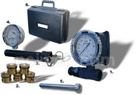
The RCM Compressed Air Survey Kit contains:
- Series 7000 RCM Direct Reading Flo-GageTM with 3 1/2" dial
- Special aluminum body Flo-GageTM for light weight and portability
- Selection of 5 range orifices
- Aluminum inlet manifold with pressure tap for pressure compensating flow readings
- 4" pressure gauge
- Quick change aluminum pipe adapters for ease in installation and range changes
- Orifice change tool
- Rugged carrying case with instruction manual and pressure and temperature correction factors
- Specifications
- Accuracy ±3% F.S.
- Pipe size 1", 2” or 3”
- 100% dial (not shown)
- Flow ranges 5 customer selected
- (max 400, 2000, 4000 SCFM for 1”, 2”, 3” respectively)
- Calibrated pressure 100 psig.
- Calibrated temperature 80° F
- 4" pressure gauge suitable for field recalibration, accuracy ±1% F.S.
- Shipping Weight 8, 10 and 20 lbs. respectively
- Models
- With pressure gauge
- 1-SK1, 2-SK1, 3-SK1
- Without pressure gauge
- 1-SK2, 2-SK2, 3-SK2
SPECIFICATIONS
- FLO-GAGE
- Accuracy ±3% F.S.
- Repeatability ±1% F.S.
;Standard ;Optional
- Pressure, max. ;180 psig (12.6 kg/cm2) ;400 psig, (28.1 kg/cm2)
- Pressure, min. ;10 psig (0.67 kg/cm2) ;10 psig, (0.67 kg/cm2)
- Temperature, max.* ;212oF (100oC) ;350oF (177oC)
- *Higher temperature available with Option R2. Consult factory.
- Temperature, min. ;-30oF (-34oC) ;-80oF (-62oC)
- Protect from freezing liquids
TRANSMITTER ;(Option W, X, Y, Z) ;(Option W2 and W3)
- Accuracy
- Horizontal Flow ;±3% F.S. above 30% F.S. ;±3% F.S. above 15% F.S.
- Vertical Flow ; ±5% F.S. above 30% F.S. ;±3% F.S. above 15% F.S.
- Ambient temp. limit ; 120oF, 50oC ;120oF, 50oC
- Current output ; 4-20mA into 800 ohms max. ;4-20mA into 650 ohms max. (350 ohms max with option RW3)
- Contact rating ;3.0 amp @ 24V, 1.0 amp
- (hi/lo) ;@ 117V, 0.5 amp @ 230V
- Frequency output ;1000 Hz F.S. 5 V peak,
- ;270 μs on time
- Electrical rating ;General purpose ;Intrinsic safety for Class I
- ; ; ;Div I Groups A,B,C,D; Class II
- ; ; ;Div I Groups E,F,G;
- ; ; ;EEx ia IIC T3
- Power input ;100mA, 24 Vdc per meter. ;25mA, 24 Vdc per meter.
- REED SWITCHES (Option 1S2, 2S2)
- Setability ;±5% F.S.
- Repeatability ;±1% F.S.
- Hysteresis ;7 to 13% F.S.
- Contact Rating ;10 watts
- Voltage ;175 vdc - max.
- ;125 Vac - max.
- Current ;350mA max. switching
CONSTRUCTION SPECIFICATIONS
- ;Standard ;Options
- Housing ;Super ABS ;Epoxy coated
- ;UV stabilized ;aluminum
- Body ;Bronze ;Monel, 316 SS
- Bellows ;Bronze ;Monel, 316 SS,
- ; ;Inconel
- Seals ;Buna-N ;Viton, EPR,
- ; ;Teflon
- Crystal ;Polycarbonate ;None
- Gear Movement ;Bronze ;316 SS
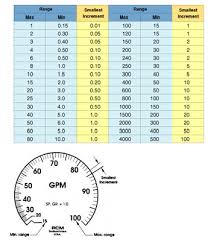
Dials And Scales
If you require further information on this product or would like a quotation, please contact dp-flow on:
email: [email protected]
sales +44(0)1608 544222
Supplied by DP-Flow