Intelligent Differential Pressure Transmitter IDP10
Manufactured by![]()
The I/A Series® Model IDP10 is an intelligent, two-wire d/p Cell® transmitter that provides precise, reliable, measurement of differential pressure, and transmits a 4 to 20 mA output signal with HART, FoxCom™, and FOUNDATION fieldbus, communication protocols, software selectable, for remote configuration and monitoring. Long-term stability with drift is less than 0.05% of URL per year for 5-years.
Key Benefits
- Silicon strain gauge sensors successfully field proven in many thousands of installations.
- Simple, elegant sensor packaging uses very few parts to achieve exceptionally high reliability
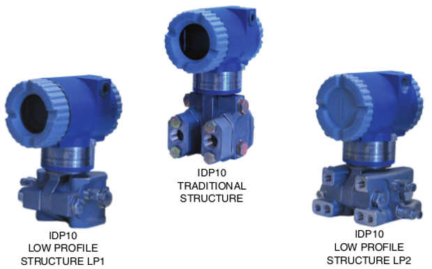
- Transmitter available with traditional or low profile structures (see photos above).
Aluminum housing has durable, corrosion resistant epoxy finish; 316 ss housing also available; both meet NEMA 4X and IP66 ratings. - Can be provided as a sealed measurement system with numerous configurations of direct connect or capillary connected seals available.
SIL2-Certified Transmitter offered as an option. - Optional mounting bracket sets allow pipe, surface, or manifold mounting of transmitter.
- Remote configuration with HART communication protocol in a single loop or multidrop mode; or
locally via optional LCD indicator. - Multi-marking is available for FM, CSA, and ATEX intrinsically safe installations. The user determines
and permanently marks on the data plate the certification to be applied. - User-entered cutoff point from 0 to 20% of maximum flow.
- Dual Seal certified by CSA to meet ANSI/ISA 12.27.01-2003 requirements.
- Industry standard 316L ss, Co-Ni-Cr, Nickel alloy (equivalent to Hastelloy® C(1)), Monel, or Tantalum
sensor materials, depending on transmitter structure. - Hastelloy is a registered trademark of Haynes International, Inc.
- Complies with NAMUR NE 21 interference immunity requirement, and NAMUR NE 43 for analog output overrange and underrange annunciations.
- CE Marked; complies with applicable EMC, ATEX, and PED European Directives.
- Complies with Electromagnetic Compatibility Requirements of European EMC Directive 2004/108/EC by conforming to the following EN and IEC Standards: EN 61326-1, and IEC 61000-4-2 through 61000-4-6.
- Designed for hazardous area installations. Versions available to meet Agency flameproof and
zone requirements.Liquid Crystal Display (LCD) digital indicator with on-board pushbutton configuration and calibration. - NEMA 4X and IEC IP66 durable epoxy-coated aluminum, or 316 ss housings.
- Co-Ni-Cr, 316L ss, and Nickel alloy (equivalent to Hastelloy®(1)) sensor materials for all transmitters.
- Integral process connections for sanitary, and pulp/paper installations.
- Choice of Mounting Styles: IDP10 for compact light weight and direct-to-process mounting (bracket optionally available
- Rugged & Dependable: Field-proven silicon strain gauge technology and corrosion-resistant epoxy finish
- Superior Performance: High accuracy to 0.05% of calibrated span in the digital linear mode, and 0.06% of calibrated span in the 4 to 20 mA linear mode.
- Rugged & Dependable: Ambient temperature effects to -29 to +82C (-20 to +180F) of normal operating conditions.
- Best in the industry - 5 year warranty
I/A Series PRESSURE TRANSMITTER FAMILY
The I/A Series Electronic Pressure Transmitters are a complete family of d/p Cell, gauge, absolute,
multirange, multivariable, and premium performance transmitters, as well as transmitters with remote or
direct connect seals, all using field-proven silicon strain gauge sensors and common topworks.
MODULAR ELECTRONICS
A common HART electronics module is used for all HART Pressure Transmitters. Also, because all configuration and calibration data is stored in the sensor, you can replace a HART module with another HART module without transmitter reconfiguration or recalibration.
Furthermore, if your needs change, the modular design allows easy migration to other standards - including FoxComTM, FOUNDATION fieldbus, and analog 4 to 20 mA or 1 to 5 V dc versions.
HART Communication Protocol Version -T Electronics
Version -T, 4 to 20 mA with HART communications,allows direct analog connection to common receivers while still providing full Digital Communications using a HART Communicator, PC-based configurator, or optional LCD Indicator.
In addition to HART Protocol, Invensys also offers transmitters with other protocols as described below.
FoxCom Version, Software Configurable for Digital and 4 to 20 mA Output (-D Electronics)
Provides measurement integration with an II/A Series system, or allows direct analog connection to common receivers while still providing full Intelligent
Transmitter digital communication with a PC-based configurator. Refer to PSS 2A-1C14 A.
FOUNDATION Fieldbus Version (-F Electronics)
This is a FISCO/FNICO compliant all digital, serial, two-way communication system which interconnects field devices such as transmitters, actuators, and controllers. It is a local area network (LAN) with built-in capability to distribute control application across the network. Refer to PSS 2A-1C13 E.
Analog Output Version (-A Electronics)
Provides a 4 to 20 mA analog output and includes a standard LCD Indicator to provide transmitter configuration directly from on-board pushbuttons. refer to PSS 2A-1C14 C.
Analog Output Version (-V Electronics)
A low power, low voltage transmitter that draws no more than 3 mA, and transmits a 1 to 5 V dc output signal. Refer to PSS 2A-1C13 D.
HART INTELLIGENT MODULE CONFIGURED FOR 4 TO 20 mA OUTPUT
Measurements and diagnostics are available from the HART Communicator connected to the two-wire loop carrying the 4 to 20 mA measurement signal by using a bidirectional digital signal superimposed on the 4 to 20 mA current signal.
Multiple measurements are transmitted digitally, including not only the primary measurement in either pressure or flow units, but also the electronics and sensor temperatures which can be used to monitor external heat tracing equipment. Complete transmitter diagnostics are also communicated. Configuration and reranging can be accomplished with the Communicator, PC-based configurator, or Digital Indicator (with pushbuttons) option.
HIGH PERFORMANCE
Transmitters are accurate to ±0.05% of calibrated span in the digital linear mode, and ±0.060% of calibrated span in the 4 to 20 mA linear mode, as well as microprocessor-based correction to achieve excellent ambient temperature compensation.
OPTIONAL SIL2 TRANSMITTERS
Modern industrial processes tend to be technically complex and have the potential to inflict serious harm to persons or property during a mishap. The IEC 61508 standard defines safety as “freedom from unacceptable risk.” SIL2 pressure transmitters with HART communication protocol, in conjunction with Triconex Safety Systems, provide integrated solutions for safety and critical control applications. The integrated solution is certified as interference-free from the 4 to 20 mA loop; this guarantees the integrity of the safety system and the safety of the controlled process. The integrated design allows uninterrupted operation of the safety function, while allowing access to device level information via HART commands. The solution permits interface of device diagnostics with asset management systems without compromising functional safety. Select Option -S2 for a SIL2- Certified HART Transmitter. A copy of the certification is available via Auxiliary Specification (AS) Code CERT-S.
WIDE MEASUREMENT RANGE WITH A MINIMUM OF SENSORS
Five d/p range sensors provide measurement spans from 0.12 to 21000 kPa (0.018 to 300 psi). The high turndown capability of the transmitter means that nearly all d/p applications can be satisfied with only these five ranges, greatly simplifying your spare transmitter and spare parts requirements.
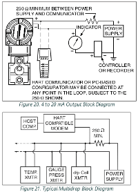
MULTIDROP COMMUNICATIONS
Either point-to-point (Figure 20) or multidropping (Figure 21) is permitted. Multidropping is the connection of several transmitters to a single communications line. Communications between the host computer and transmitter takes place digitally, with the analog output of the transmitter fixed. With HART communication protocol, up to fifteen transmitters can be connected on a single twisted pair of wires or over leased telephone lines.
OPTIONAL MOUNTING BRACKET SETS
In addition to the standard style mounting bracket sets optionally offered with these transmitters, a unique universal style mounting bracket has been developed to allow wide flexibility in transmitter mounting configurations consistent with installation requirements. All mounting bracket sets allow mounting to a surface, pipe, or manifold. Refer to Dimensions - Nominal section.
PROCESS CONNECTORS
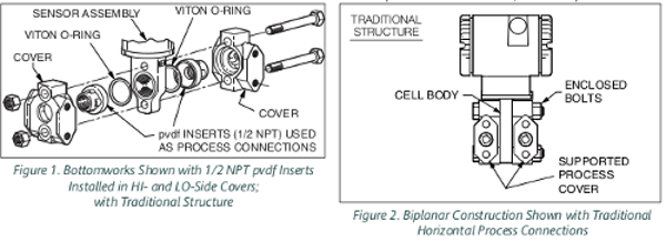
Removable, gasketed process connectors allow a wide range of selections, including 1/4 NPT, 1/2 NPT, Rc 1/4, Rc 1/2, and weld neck connections. For highly corrosive chemical processes when a traditional structure is used (see transmitter structures further in document), two 1/2 NPT pvdf inserts (Figure 1) are installed in both 316 ss covers and are used as the process connectors. In these applications, tantalum is used as the sensor diaphragm material.
SENSOR CORROSION PROTECTION
For traditional structure, choice of 316L ss, Co-Ni-Cr, nickel alloy (equivalent to Hastelloy® C), Monel, Gold-Plated 316L ss, and Tantalum materials. High corrosion resistance of Co-Ni-Cr (TI 037-078) means long service life in many difficult applications without the extra cost for exotic materials. See TI 037-75b for process applicability with Co-Ni-Cr and other process wetted materials.
For low profile structures LP1 and LP2, 316L ss and nickel alloy (equivalent to Hastelloy® C) are offered as sensor materials. Refer to Transmitter Structures section that follows for description and application of traditional and low profile (LP1 and LP2) structures.
OPTIONAL LCD DIGITAL INDICATOR
A two-line digital indicator (Figure 22) with on-board pushbuttons is available to display the measurement with a choice of units. The pushbuttons allow zero and span adjustments, as well as local configuration without the need for a HART Communicator or PC- based configurator.
EASE OF INSTALLATION
Rotatable Topworks allows transmitter installation in tight places, allows indicator to be positioned in preferred direction, and eases field retrofit. Two Conduit Entrances offer a choice of entry positions for ease of installation and self-draining of condensation regardless of mounting position and topworks rotation. Wiring Guides and Terminations provide ease of wire entry and support, plenty of space to work and store excess wire, and large, rugged screw terminals for easy wire termination.
UNIQUE PROCESS COVER AND CELL BODY DESIGN
Biplanar Construction (Figure 2) maintains the traditional horizontal process connections and vertical mounting by providing a cell body contained between two process covers, while still achieving light weight, small size, and high standard static pressure rating of 25 MPa (3625 psi). This provides easy retrofit of any conventional differential pressure transmitter, and also is easily mounted in the horizontal position with vertical process connections, when required.
Process Covers (Figure 2) are fully supported by the cell body over their entire height. This prevents bending and results in a highly reliable seal. Also, this provides dimensional stability to the process covers, nsuring that they will always mate properly with 3- valve bypass manifolds.
Process Cover Bolts (Figure 2) are enclosed to minimize corrosion and to minimize early elongation with rapid temperature increases. The design makes it less likely for the transmitter to release process liquid during a fire.
Process Cover Gaskets are ptfe as standard; ptfe provides nearly universal corrosion resistance, and eliminates the need to select and stock various elastomers to assure process compatibility.
Light Weight provides ease of handling, installation, and direct mounting without requiring costly pipe stands.
TRANSMITTER STRUCTURES
Traditional and low profile structures (LP1 and LP2) are offered to accommodate and to provide flexibility in transmitter installations. See paragraphs that follow.
Traditional Structure
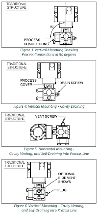
The traditional structure (Figure 3) utilizes the right angle design common to most DP transmitters in use throughout the world. Process connections are oriented 90 degrees from the transmitter centerline. This traditional structure makes it easy to retrofit any transmitters of similar design. Sensor cavity venting and draining is provided for both vertical and horizontal transmitter installation, using innovative tangential connections to the sensor cavity (Figures 4 and 5). Optional side vents are offered for sensor cavity venting in the upright position (Figure 6). An extensive variety of process wetted materials are available for the process covers on this highly versatile and widely used transmitter.
Low Profile Structures
The low profile structures utilize an in-line design, placing the process connections in line with the transmitter centerline (Figures 7 and 8). This allows mounting of the transmitter in the upright position with the process connections facing downward, for connection to vertical process piping or for mounting directly to a three- or five-valve manifold. The low profile structures provide a mounting style similar to that used by competitive CoplanarTM transmitters. This makes it easy to select Foxboro transmitters for both retrofit and new applications where this type of installation is desired. Transmitters with the low profile structure can be attached directly to existing, installed Coplanar manifolds, such as the Rosemount Model 305RC or Anderson Greenwood Models MB3, MB5G, and MB5P, by use of an optional adapter plate (Figure 9). Also, when assembled to the same process piping or manifold as a Coplanar transmitter, one of the electrical conduit connections is located within ± one inch of the similar conduit connection on the competitive transmitter, assuring ease of retrofit or conformance with installation design drawings.
All parts making up the low profile versions are Low Profile Structure LP1 is a compact, inexpensive, identical to the parts in the traditional version except lightweight design for direct mounting to a separately for the process covers and the external shape of the mounted manifold or process piping. These sensor cell body. transmitters are not typically bracket-mounted. For user convenience, two types of low profile structures are offered, type LP1 and LP2. The process covers are the only transmitter parts that differ between structure types LP1 and LP2.
Refer to the sections that follow for further descriptions of low profile structures LP1 and LP2.
Low Profile Structure LP1 – Direct Mount
Low Profile Structure LP1 is a compact, inexpensive, lightweight design for direct mounting to a separately mounted manifold or process piping. These transmitters are not typically bracket-mounted. They are supplied as standard with a single vent/drain screw in the side of each process cover. In conjunction with the standard tangential venting and draining design, they are suitable for mounting either vertically (Figure 10) or horizontally, and are suitable for nearly all applications, including liquids, gases, and steam. For horizontal installation, they can simply be “turned over” (rotated 180 degrees - Figures 11 and 12) to orient the high and low pressure sides in the preferred locations. There is no need to unbolt process covers. The topworks housing can also be rotated, as shown, to orient the conduit connections in the desired position. In the vertical, upright position, they are also self- draining and are ideal for gas flow rate service, when directly mounted to a manifold located above the horizontal pipeline. The vent screw can be omitted for this or other applications, if desired.
Low Profile Structure LP2 – Bracket or Direct Mount
Low Profile Structure LP2 is a universal design for either bracket or direct mounting. Drilled and tapped mounting holes facilitate mounting to either new or existing Foxboro brackets (Options -M1, -M2, and -M3), as well as standard brackets supplied with existing Coplanar transmitters. See Figure 13 and Figure 14. These transmitters can also be directly mounted to manifolds or process piping and are available with the same optional adapter used with low profile structure LP1 to fit existing Coplanar manifolds (Figure 15). For extra convenience, they use a full-featured vent and drain design, with separate vent and drain screws positioned in each cover for complete venting or draining directly from the sensor cavity. They are normally recommended for upright, vertical installation.
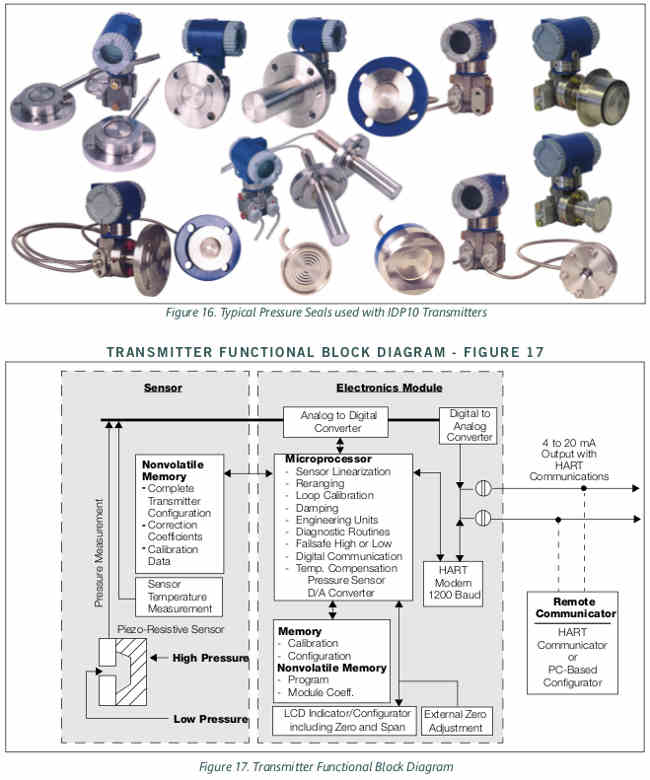
PRESSURE SEALS
Pressure seals are used with transmitters having a traditional structure (see “TRANSMITTER STRUCTURES” on page 5) when it is necessary to keep the transmitter isolated from the process. A sealed system is used for a process fluid that may be corrosive, viscous, subject to temperature extremes, toxic, sanitary, or tend to collect and solidify. Table 1 lists the various pressure seals that can be used with an IDP10 Transmitter. To order a transmitter with seals, both a Transmitter Model Number and Seal Model Number are required. For a complete listing of pressure seal models and specifications, see PSS 2A-1Z11 A. Also see Figure 16 for typical pressure seal configurations.
Table 1. Pressure Seals Used with IDP10 Transmitters
| Direct Connect Pressure Seal Assemblies | ||
| Seal Model | Seal Description | Process Connections |
| PSFLT | Flanged, Direct Connect (Flanged Level), Flush or Extended Diaphragm | ANSI Class 150/300/600 flanges and BS/DIN PN 10/40, 10/16, 25/40 flanges |
| PSSCT | Sanitary, Direct Connect (Level Seal), Flush Diaphragm | Process Connection to Sanitary Piping with 2- or 3- Diaphragm inch Tri-Clamp |
| PSSST | Sanitary, Direct Connect (Level Seal), Extended Diaphragm | Process Connection to 2-in Mini Spud or 4-in Standard Spud; Tri-Clamp |
| Remote Mount, Capillary-Connected Pressure Seal Assemblies | ||
| Seal Model | Seal Description | Process Connections |
| PSFPS | Flanged, Remote Mount, Flush Diaphragm | ANSI Class 150/300/600 flanges and BS/DIN PN 10/40 flanges |
| PSFES | Flanged, Remote Mount, Extended Diaphragm | ANSI Class 150/300/600 flanges and BS/DIN PN 10/40, 10/16, 25/40 flanges |
| PSFAR | Flanged, Remote Mount, Recessed Diaphragm | ANSI Class 150/300/600/1500 flanges |
| PSFFR | Flanged, Remote Mount, Flush Diaphragm | ANSI Class 150/300/600 and PN 10/40 |
| PSTAR | Threaded, Remote Mount, Recessed Diaphragm | 1/4, 1/2, 3/4, 1, or 1 1/2 NPT internal thread |
| PSISR | In-Line Saddle Weld, Remote Mount, Recessed Diaphragm | Lower housing of seal is in-line saddle welded to nominal 3- or 4-inch (and larger) Pipe |
| PSSCR | Sanitary, Remote Mount, Flush Diaphragm | Process Connection secured with a Tri-Clamp to a 2- or 3-inch pipe |
| PSSSR | Sanitary, Remote Mount, Extended Diaphragm Process Connection to 2-in Mini Spud or 4-in Standard Spud; Tri-Clamp | |
FUNCTIONAL SPECIFICATIONS
Span Limits for IDP10 d/p Cell Transmitters
| Span Code | kPa | psi | mbar | mmHg | mmH2O | inH2O |
| A(a) | 0.12 and 7.5 | 0.018 and 1.1 | 1.2 and 75 | 0.93 and 56 | 12 and 750 | 0.5 and 30 |
| B | 0.87 and 50 | 0.125 and 7.2 | 8.7 and 500 | 6.5 and 375 | 87 and 5000 | 3.5 and 200 |
| C | 7 and 210 | 1 and 30 | 70 and 2100 | 50 and 1500 | 700 and 21,000 | 28 and 840 |
| Span | MPa | psi | bar or kg/cm2 | mHg | mH2O | ftH2O |
| Code | ||||||
| D | 0.07 and 2.1 | 10 and 300 | 0.7 and 21 | 0.5 and 15 | 7 and 210 | 23 and 690 |
| E(b) | 0.7 and 21(b) | 100 and 300 (b) | 7 and 210 (b) | 5 and 150 (b) | 70 and 2100(b) | 230 and 6900 (b) |
(a) Span Limit Code “A” not available when pressure seals are selected.
(b) When certain options are specified, the upper span and range limits are reduced as shown in the “Options Impact” table below.
Range Limits for IDP10 d/p Cell Transmitters (a)
| Span Code | kPa | psi | mbar | mmHg | mmH2O | |
| A(b) | -7.5 and +7.5 | -1.1 and +1.1 | -75 and +75 | -56 and +56 | -750 and +750 | -30 and +30 |
| B | -50 and +50 | -7.2 and +7.2 | -500 and +500 | -375 and +375 | -5000 and +5000 | -200 and +200 |
| C | -210 and +210 | -30 and +30 | -2100 and +2100 | -150 and +150 | -21 000 and +21,000 | -840 and +840 |
| Span Code | MPa | psi | bar or kg/cm2 | mHg | mH2O | ftH2O |
| D | -0.21 and +2.1 | -30 and +300 | -2.1 and +21 | -1.5 and +15 | -21 and +210 | -69 and +690 |
| E(c) | -0.21 and 21 (c) | -30 and +3000 (c) | -2.1 and +210 (c) | -1.5 and +150 (c) | -21 and +2100 (c) | -69 and +6900 (c) |
(a) Positive values indicate HI side of sensor at the high pressure, and negative values indicate LO side of sensor at the high pressure.
(b) Span Limit Code “A” not available when pressure seals are selected.
(c) When certain options are specified, the upper span and range limits are reduced as shown in the “Options Impact” table below.
Impact of Certain Options on Span and Range Limits (a)
| Option | Description (Also see Model Code) | Span and Range Limits Derated to: |
| -B3 | B7M Bolts and Nuts (NACE) | 20 MPa (2900 psi, 200 bar, or kg/cm2) |
| -D1 | DIN Construction | 16 MPa (2320 psi, 160 bar or kg/cm2) |
| -D5 or -B1 | DIN Construction or 316 ss Bolting | 15 MPa (2175 psi, 150 bar or kg/cm2) |
| -D2, -D4, -D6, or -D8 (a) | DIN Construction (a) | 10 MPa (1500 psi, 100 bar or kg/cm2) (a) |
(a) Refer to Model Code section for application and restrictions related to the items listed in the table.
Maximum Static and Proof Pressure Ratings for IDP10 d/p Cell Transmitters(2)
(a) Proof pressure ratings meet ANSI/ISA Standard S82.03-1988. Unit may become nonfunctional after application of proof pressure.
Maximum Static and Proof Pressure Ratings for IDP10 d/p Cell Transmitters(2)
| Transmitter Configuration (See Model Code for Description of Options) | Static Pressure Rating | Proof Pressure Rating (a) | ||||
| MPa | psi | bar or kg/cm2 | MPa | psi | bar or kg/cm2 | |
| With Option -D9 or -Y | 40 | 5800 | 400 | 100 | 14500 | 1000 |
| Standard or with Option -B2, -D3, or -D7 | 25 | 3625 | 250 | 100 | 14500 | 1000 |
| With Option -B3 | 20 | 2900 | 200 | 70 | 11150 | 700 |
| With Option -D1 | 16 | 2320 | 160 | 64 | 9280 | 640 |
| With Option -B1 or -D5 | 15 | 2175 | 150 | 60 | 8700 | 600 |
| With Option -D2, -D4, -D6, or -D8 | 10 | 1500 | 100 | 40 | 6000 | 400 |
| With Structure Codes 78 and 79 (pvdf insert) | 2.1 | 300 | 21 | 8.4 | 1200 | 84 |
Output Signal and Configuration
4 to 20 mA with HART Communications. When configured for multidrop applications, the mA signal is fixed at 4 mA to provide power to the device. Configurable using a HART Communicator, PC-based Configurator, or optional LCD Indicator with on-board pushbuttons.
Field Wiring Reversal
No transmitter damage.
Suppressed Zero and Elevated Zero
Suppressed/elevated zero ranges are acceptable as long as the Span/Range Limits are not exceeded.
Electronics and Sensor Temperatures
Readable from the HART Communicator, PC-based Configurator, or optional LCD Indicator with on-board pushbuttons. Measurement is transmitter temperature, not necessarily process temperature.
Adjustable Damping
Response time is normally 0.75 s, or electronically adjustable setting of 0.00 (none), 0.25, 0.50, 1, 2, 4, 8, 16, or 32 seconds, whichever is greater, for a 90% recovery from an 80% input step as defined in ANSI/ISA S51.1. (For 63.2% recovery, 0.50 s with sensors B to E, and 0.60 s with Sensor A.)
Zero and Span Adjustments
Zero and span adjustments can be initiated from the HART Communicator, PC-based Configurator, or optional LCD Indicator having on-board pushbuttons.
Zeroing for Nonzero-Based Ranges
Dual Function Zeroing allows zeroing with the transmitter open to atmosphere, even when there is a nonzero-based range. This greatly simplifies position effect zeroing on many pressure and level applications. It applies to optional LCD Indicator with on-board pushbuttons and optional External Zero Adjustment.
Current Outputs for Overrange, Fail, and Offline Conditions
| OFFLINE | User configurable between 4 and 20 mA |
| SENSOR FAILURE | User configurable to Fail LO or Fail HI |
| FAIL LO | 3.60 mA |
| UNDERRANGE | 3.80 mA |
| OVERRANGE | 20.50 mA |
| FAIL HI | 21.00 mA |
Write Protect Jumper
Can be positioned to lock out all configurators from making transmitter database changes. This makes transmitter suitable for Safety Shutdown System Applications that require this feature.
(2) Refer to Model Code section for application and restrictions related to the items listed in the table.
Square Root Low Flow Cutoff
User configurable using HART Communicator, PC- based Configurator, or optional LCD with on-board pushbuttons to provide:
User settable for cutoff to zero at any flow rate between 0 and 20% of maximum flow.
Cutoff to zero at flows <10% of maximum flow (1% of maximum differential pressure).
Or active point-to-point line between zero and 20% of maximum flow (4% of maximum differential pressure).
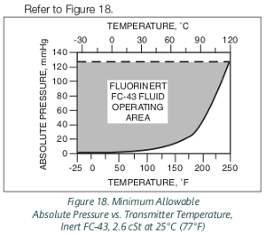
Minimum Allowable Absolute Pressure vs.Transmitter Temperature
With Silicone Fill Fluid Full vacuum: up to 121°C (250°F)
With Inert Fill Fluid Refer to Figure 18.
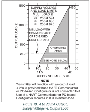
Supply Voltage Requirements and External Loop Load Limitations
Minimum voltage shown in Figure 19 is 11.5 V dc. This value can be reduced to 11 V dc by using a plug- in jumper across the test receptacles in the field wiring compartment terminal block. See Figure 23.
Configuration and Calibration Data
All factory characterization data and user configuration and calibration data are stored in the sensor, as shown in the transmitter block diagram, Figure 17. This means that the electronics module may be replaced, with one of like type, without the need for reconfiguration or recalibration. Replacing the module can affect accuracy by a maximum of 0.20% of span. Error can be removed by a mA trim that does not require application of pressure.
Electronics Upgradeability
As stated above, all factory characterization data is stored in the sensor and is accessed by each electronics module type. This means that electronics modules can be changed from one type to another, allowing for easy upgrade from an analog output type to a fully intelligent type module. Changing module types may require reconfiguration and recalibration, but all factory characterization data is retained.
Communications
Configurable for either Analog (4 to 20 mA) or Multidrop Mode. Digital communications is provided in both modes based upon the FSK (Frequency Shift Keying) technique which alternately superimposes one of two different frequencies on the uninterrupted current carried by the two signal/power wires.
Analog Mode (4 to 20 mA)
The output signal is updated 30 times per second. Digital communications between the transmitter and HART Communicator or PC- based Configurator is rated for distances up to 3050 m (10,000 ft). The communications rate is 1200 baud and requires a minimum loop load of 250 ohms. See Figure 20.
Multidrop Mode (Fixed Current)
Multidrop Mode supports communications with up to 15 transmitters on a single pair of signal/power wires. The digital output signal is updated 4 times per second and carries pressure measurement and sensor/electronics temperatures (internal recalculation rate for temperature is once per second). Communications between the transmitter and the system, or between the transmitter and HART Communicator or PC-based Configurator, is rated for distances up to 1525 m (5000 ft). The digital communications rate is 1200 baud and requires a minimum loop load of 250 ohms. See Figure 21.
Remote Communications
The HART Communicator or PC-based Configurator has full access to all of the “Display” and “Display and Reconfigure” items listed below. It may be connected to the communications wiring loop and does not disturb the mA current signal. Plug-in connection points are provided on the transmitter terminal block.
“Display” Items
Process Measurement in Two Formats
Transmitter Temperatures (Electronics and Sensor)
mA Output
“Display and Reconfigure” Items
Zero and Span Calibration
Reranging without Pressure
Linear or Square Root Output
Choice of Pressure and Flow EGU
Electronic Damping
Temperature Sensor Failure Strategy
Failsafe Direction
Tag, Descriptor, and Message
Date of Last Calibration
Configuration Capability
Calibrated Range
Input range within Span and Range Limits
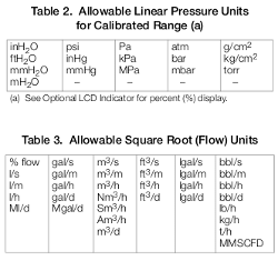
One of pressure units shown in Table 2
Output Measurement #1 – Digital Primary Variable and 4 to 20 mA
Mode: Linear or Square Root
Units for Linear Mode: One of pressure units shown in Table 2
Units for Square Root Mode: One of flow units shown in Table 3
Output Measurement #2 – Digital Secondary Variable
Mode: Linear or Square Root (independent of Measurement #1)
Units for Linear Mode: One of pressure units shown in Table 2
Units for Square Root Mode: One of flow units shown in Table 3..Table 2. Allowable Linear Pressure Units for Calibrated Range (a)
Table 3. Allowable Square Root (Flow) Units
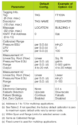
Optional Custom Configuration (Option -C2)
For the transmitter to be custom configured by the factory, the user must fill out a data form. If this option is not selected, a standard default configuration will be provided; for example, see the table below. Any of the above configurable parameters in the table below can easily be changed using the HART Communicator or PC-based Configurator.
Optional LCD Digital Indicator (Figure 22)
Indicator provides:
Two Lines; Five numeric characters on top line (four when a minus sign is needed); and seven alphanumeric characters on bottom line.
Measurement Readout; Value displayed on top line, and units label displayed on bottom line.
Configuration and Calibration prompts.
Pushbuttons (two) provide the following configuration and calibration functions:
Zero and Span settings, non-interactive to automatically set output to either 4 mA or 20 mA using the “NEXT” and “ENTER” pushbuttons.
4 and 20 mA Jog Settings, allowing the user to easily increment the mA output signal up or down in fine steps to match a value shown on an external meter.
Linear or Square Root Output
User-entered cutoff point from 0 to 20% of maximum flow.
Forward or Reverse Output
Damping Adjustment
Enable/Disable Optional External Zero
Temperature Sensor Failure Strategy
Failsafe Action
Units Label (Bottom Line of Display)
Settable Lower and Upper Range Values for Transmission and Display (Top Line)
Reranging
Percent (%) Output
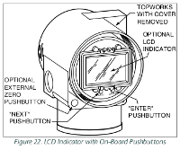
Optional External Zero Adjustment
An external pushbutton (Figure 22) mechanism is isolated from electronics compartment and magnetically activates an internal reed switch through the housing. This eliminates a potential leak path for moisture or contaminants to get into the electronics compartment. This zero adjustment can be disabled by a configuration selection.
OPERATING, STORAGE, AND TRANSPORTATION CONDITIONS
(a) When Traditional Structure Codes 78/79 (pvdf inserts in Hi- and Lo-side process covers) are used, maximum overrange is 2.1 MPa
(300 psi), and temperature limits are -7 and +82°C (20 and 180°F); when DIN Construction Options D2/D4/D6/D8 are used,
temperature limits are 0 and 60°C (32 and 140°F).
(b) Normal Operating Conditions and Operative Limits are defined per ANSI/ISA 51.1-1979 (R1993).
(c) Selection of Option -J extends the low temperature operative limit of transmitters with silicone filled sensors down to -50°C (-58°F).
Performance is not assured below -29°C. Sensor damage may occur if process is frozen.
(d) Although the LCD will not be damaged at any temperature within the “Storage and Transportation Limits”, updates will be slowed and
readability decreased at temperatures outside the “Normal Operating Conditions”.
(e) With topworks cover on and conduit entrances sealed.
(f) 11.5 V dc can be reduced to 11 V dc by using a plug-in shorting bar; see “Supply Voltage Requirements” section and Figure 23.
(g) Sensor process wetted diaphragms in a vertical plane.
(h) Refer to the Electrical Safety Specifications section for a restriction in ambient temperature limits with certain electrical certifications.
PERFORMANCE SPECIFICATIONS
Zero-Based Calibrations; Cobalt-Nickel-Chromium or Stainless Steel Sensor w/Silicone Fluid; Under
Reference Operating Conditions unless otherwise Specified. URL = Upper Range Limit and Span = Calibrated
Accuracy
(a) Accuracy includes Linearity, Hysteresis, and Repeatability.
(b) Add ±0.04% for Span Code A, and ±0.02% for Span
Code E.
(c) Subtract ±0.01% for digital output accuracy.
Table 5. Accuracy (Square Root Output) (a)
(a) Accuracy includes Linearity, Hysteresis, and Repeatability.
Stability
Long term drift is less than ±0.05% of URL per year over a 5-year period.(3)
Calibration Frequency
The calibration frequency is five years. The five years is derived using the values of allowable error (% span), TPE (% span), performance margin (% span), and stability (% span/month); where: Calibration Frequency = Performance Margin /Stability = Months
(3) Add an additional 0.05% to stability specification for Span Code A.
Power-up Time
,
Less than 5 seconds for output to reach first valid measurement.
RFI Effect
The output error is less than 0.1% of span for radio frequencies from 27 to 1000 MHz and field intensity of 30 V/m when the transmitter is properly installed with shielded conduit and grounding, and housing covers are in place. (Per IEC Std. 61000-4-3.)
Supply Voltage Effect
Output changes less than 0.005% of span for each 1 V change within the specified supply voltage requirements. See Figure 19.
Vibration Effect
Total effect is ±0.2% of URL per “g” for vibrations in the frequency range of 5 to 500 Hz; with double amplitudes of 6.3 mm (0.25 in) in the range of 5 to 15 Hz, or accelerations of 3 “g” in the range of 15 to 500 Hz, whichever is smaller, for transmitter with aluminum housing; and with double amplitudes of 6.3 mm (0.25 in) in the range of 5 to 9 Hz, or accelerations of 1 “g” in the range of 9 to 500 Hz, whichever is smaller, for transmitter with 316 ss housing.
Position Effect
Any zero effect caused by mounting position can be eliminated by rezeroing. There is no span effect.
Static Pressure Effect
The zero and span shift for a 7 MPa, 1000 psi, change in static pressure is:
Span Shift
±0.15% of Reading.
Switching and Indirect Lightning Transients
The transmitter can withstand a transient surge up to 2000 V common mode or 1000 V normal mode without permanent damage. The output shift is less than 1.0%. (Per ANSI/IEEE C62.41-1980 and IEC Std. 61000-4-5.)
Ambient Temperature Effect
Total effect for a 28°C (50°F) change within Normal Operating Condition limits is:
NOTE
For additional ambient temperature effect with pressure seals are used, see PSS 2A-1Z11 A.
PHYSICAL SPECIFICATIONS
Process Cover and Connector Material (Process Wetted)
Carbon Steel, 316 ss, Monel, nickel alloy (equivalent to Hastelloy® C), or pvdf (Kynar) inserts in 316 ss covers for transmitter traditional structure; and 316 ss for transmitter low profile structures. For exceptional value and corrosion resistance, 316 ss is the least expensive material.
Process Cover and Process Connection Gaskets
Glass filled ptfe, or Viton when Structure Codes 78/79 (pvdf inserts) are used.
Process Cover Bolts and Nuts
ASTM A193, Grade B7 high strength alloy steel for bolts, and ASTM A194 Grade 2H high strength alloy steel for nuts are standard. Options include NACE Class B7M bolting, 17-4 ss bolting, and 316 ss bolting.
(4) Can be calibrated out by zeroing at nominal line pressure.
Sensor Material (Process Wetted)
Co-Ni-Cr, 316 L ss, Gold-Plated 316L ss, Monel, nickel alloy (equivalent to Hastelloy® C), or Tantalum for transmitter traditional structure; and 316L ss or nickel alloy (equivalent to Hastelloy® C) for transmitter low profile structures. For exceptional value and corrosion resistance, 316L ss is the least expensive material. Refer to TI 037-078 and TI 37-75b for information regarding the corrosion resistance of Co- Ni-Cr and other sensor materials.
Sensor Fill Fluids
Silicone Oil or Inert (FC-43)
Environmental Protection
The enclosure has the dusttight and weatherproof rating of IP66 as defined by IEC 60529, and provides the environmental and corrosion resistant protection rating of NEMA 4X.
Electronics Housing and Housing Covers
Housing has two compartments to separate the electronics from the field connections. The housing and covers are made from low copper, die-cast aluminum alloy with an epoxy finish, or from 316 ss. Buna-N O-ring seals are used to seal the threaded housing covers, housing neck, and terminal block.
Electrical Connections
Field and RTD sensor wires enter through 1/2 NPT, PG 13.5, or M20 threaded entrances, as specified, on either side of the electronics housing. Wires terminate under screw terminals and washers on terminal block in the field terminal compartment. Unused entrance is plugged to insure moisture and RFI/EMI protection. See Figure 23.
Electronics Module
Printed wiring assemblies are conformally coated for moisture and dust protection.
Mounting Position
The transmitter may be mounted in any orientation.
Approximate Mass (with Process Connectors)
4.2 kg (9.2 lb) with Traditional Structure
Add 0.1 kg (0.2 lb) with Low Profile Structure LP1
Add 0.8 kg (1.8 lb) with Low Profile Structure LP2
Add 1.1 kg (2.4 lb) with 316 ss Housing
Add 0.2 kg (0.4 lb) with LCD Indicator Option
Dimensions
See “Dimensions - Nominal” section and Dimensional Print DP 020-446.
| Description | |||
| I/A Series, Electronic d/p Cell Transmitter for Differential Pressure Measurement | |||
| Model | |||
| IDP10 | |||
| Electronics Versions and Output Signal | |||
| Intelligent; Digital, HART and 4 to 20 mA (Version -T) | -T | ||
| Structure Code - Select from one of the following six groups: | |||
| 1. Transmitter with Traditional Structure | |||
| Covers | Sensor | Fill Fluid | |
| Steel | Co-Ni-Cr | Silicone | 10 |
| Steel | Co-Ni-Cr | Inert | 11 |
| Steel | 316L ss | Silicone | 12 |
| Steel | 316L ss | Inert | 13 |
| Steel | Nickel alloy (y) | Silicone | 16 |
| Steel | Nickel alloy (y) | Inert | 17 |
| 316 ss | Co-Ni-Cr | Silicone | 20 |
| 316 ss | Co-Ni-Cr | Inert | 21 |
| 316 ss | 316L ss | Silicone | 22 |
| 316 ss | 316L ss | Inert | 23 |
| 316 ss | 316L ss, Gold Plated | Silicone | 2G |
| 316ss | Monel | Silicone | 24 |
| 316 ss | Monel | Inert | 25 |
| 316 ss | Nickel alloy (y) | Silicone | 26 |
| 316 ss | Nickel alloy (y) | Inert | 27 |
| Monel | Monel | Silicone | 34 |
| Monel | Monel | Inert | 35 |
| Nickel alloy (y) | Nickel alloy (y) | Silicone | 46 |
| Nickel alloy (y) | Nickel alloy (y) | Inert | 47 |
| Nickel alloy (y) | Tantalum | Silicone | 48 |
| Nickel alloy (y) | Tantalum | Inert | 49 |
| pvdf Insert (Kynar) | Tantalum | Silicone (Used with Process Connector Type 7) | 78(a) |
| pvdf Insert (Kynar) | Tantalum | Inert (Used with Process Connector Type 7) | 78 (a) |
| 2. Transmitter with Low Profile Structure LP1 (Not available with Pressure Seals) | |||
| Covers | Sensor | Fill Fluid | |
| 316 ss | 316L ss | Silicone | LL |
| 316 ss | 316L ss | Inert | LM |
| 316 ss | Nickel alloy (y) | Silicone | LC |
| 316 ss | Nickel alloy (y) | Inert | LD |
| 3. Transmitter with Low Profile Structure LP2 (Not available with Pressure Seals) | |||
| Covers | Sensor | Fill Fluid | |
| 316 ss | 316L ss | Silicone | 52 |
| 316 ss | 316L ss | Inert | 53 |
| 316 ss | Nickel alloy (y) | Silicone | 56 |
| 316 ss | Nickel alloy (y) | Inert | 57 |
| 4. Transmitter prepared for Foxboro Model Coded Remote Mount Seals (b)(c) | |||
| Transmitter prepared for Remote Seals on Both HI and LO Sides, Silicone Fill in Sensor | S1 | ||
| Transmitter prepared for Remote Seals on Both HI and LO Sides, Inert Fill in Sensor | S2 | ||
| Transmitter prepared for Remote Seal HI Side, 1/2 NPT Connector LO Side, Silicone Fill in Sensor | S3 | ||
| Transmitter prepared for Remote Seal HI Side, 1/2 NPT Connector LO Side, Inert Fill in Sensor | S4 | ||
| Transmitter prepared for Remote Seal LO Side, 1/2 NPT Connector HI Side, Silicone Fill in Sensor | S5 | ||
| Transmitter prepared for Remote Seal LO Side, 1/2 NPT Connector HI Side, Inert Fill in Sensor | S6 | ||
| 5. Transmitter Prepared for Foxboro Model Coded Direct Connect Seals (b) | |||
| PSFLT, PSSCT, or PSSST Direct Connect Seal on HI Side; 1/2 NPT Process Connector LO Side; Silicone Fill | F1 | ||
| PSFLT, PSSCT, or PSSST Direct Connect Seal on HI Side; 1/2 NPT Process Connector LO Side; Inert Fill | F2 | ||
| PSFLT, PSSCT, or PSSST Direct Connect Seal on HI Side; Remote Seal with Capillary LO Side; Silicone Fill | F3 | ||
| PSFLT, PSSCT, or PSSST Direct Connect Seal on HI Side; Remote Seal with Capillary LO Side; Inert Fill | F4 | ||
| 6. Transmitter Prepared for non-Foxboro Seals | |||
| Remote Seals on High and Low Sides; Silicone Fill in Sensor | SA | ||
| Remote Seals on High and Low Sides; Inert Fill in Sensor | SB | ||
| Remote Seal on High Side and 1/2 NPT Connector on Low Side, Silicone Fill in Sensor | SC | ||
| Remote Seal on High Side and 1/2 NPT Connector on Low Side, Inert Fill in Sensor | SD | ||
| Remote Seal on Low Side and 1/2 NPT Connector on High Side, Silicone Fill in Sensor | SE | ||
| Remote Seal on Low Side and 1/2 NPT Connector on High Side, Inert Fill in Sensor | SF | ||
| Span Limits (Differential Pressure Units) | |||
| kPa | inH2O | mbar | |
| 0.12 and 7.5 | 0.5 and 30 | 1.2 and 75 | A (e) |
| 0.87 and 50 | 3.5 and 200 | 8.7 and 500 | B |
| 7 and 210 | 28 and 840 | 70 and 2100 | C |
| MPa | psi | bar or kg/cm2 | |
| 0.07 and 2.1 | 10 and 300 | 0.7 and 21 | D |
| 0.7 and 21 | 100 and 3000 | 7 and 210 | E (f) |
| Process Connector Type (Material Same as Process Cover Material) (g) | |||
| See below: | |||
| For d/p: No connectors; both covers tapped for 1/4 NPT (316 ss only, no side vents) | 0 | ||
| Flange Mount Hi Side: 1/2 NPT, 316 ss Process Connector on Lo Side (F1 and F2 only) | |||
| Flange Mount Hi Side: No connectors; both sides prepared for seals (F3 and F4 only) | |||
| Two Remote Seals: No connectors; both covers tapped for capillary connection (S1, S2, SA, SB only) | |||
| One Remote Seal: 1/2 NPT, 316 ss Process Connector on Side Opposite Seal (S3 to S6, SC to SF only) | |||
| 1/4 NPT, Not with Structure Codes 46 to 49, 78, 79; or pressure seals | 1 | ||
| 1/2 NPT, Not with Structure Codes 78 or 79, or pressure seals | 2 | ||
| Rc 1/4, Not with Structure Codes 46 to 49, 78, 79; or pressure seals | 3 | ||
| Rc 1/2, Not with Structure Codes 78 or 79, or pressure seals | 4 | ||
| 1/2 Schedule 80 Welding Neck, Not with Structure Codes 46 to 49, 78, 79; or pressure seals | 5 | ||
| None; pvdf Insert tapped for 1/2 NPT/Process Inlet on Side of 316 ss Process Covers (only with 78/79 above) | 6 | ||
| Conduit Connection and Housing Material | |||
| 1/2 NPT Conduit Connection, Aluminum Housing | 1 | ||
| PG 13.5 Conduit Connection, Aluminum Housing (With Electrical Safety Codes E, D, M, and N only) | 2 | ||
| 1/2 NPT Conduit Connection, 316 ss Housing | 3 | ||
| PG 13.5 Conduit Connection, 316 ss Housing (With Electrical Safety Codes E, D, M, and N only) | 4 | ||
| M20 Conduit Connection, Both Sides, Aluminum Housing (With Electrical Safety Codes E, D, M, and N only) | 5 | ||
| M20 Conduit Connection, Both Sides, 316 ss Housing (With Electrical Safety Codes E, D, M, and N only) | 6 | ||
| Electrical Safety - Also see Electrical Safety Specifications section for descriptions | |||
| Model | |||
| ATEX II 1 GD, EEx ia IIC, Zone 0; or II 1/2 GD, EEx ib IIC, Zone 0/1 | E | ||
| ATEX II 2 GD, EEx d IIC, Zone 1 (d) | D | ||
| ATEX II 3 GD, EEx nL IIC, Zone 2 | N | ||
| ATEX Multiple Certifications (includes ATEX Codes E, D, and N) (d) | M | ||
| (See Electrical Safety Specifications section for user marking) | |||
| CSA Certified Division 1 intrinsically safe, explosionproof, dust-ignitionproof, and Division 2, Classes I, II, and III. | C | ||
| CSA Zone Certified Ex d IIC; and all certifications of Code C above, Ex ia and Ex n (d). | B | ||
| FM approved Division 1 intrinsically safe, explosionproof, dust-ignitionproof, and nonincendive, Division 2. | F | ||
| FM approved AEx d IIC; and also all approvals of Code F above, AEx ia (d). | G | ||
| IECEx intrinsically safe; Ex ia IIC | T | ||
| IECEx protection n; Ex nL IIC | U | ||
| IECEx flameproof; Ex d IIC | V | ||
| Multi-marked for ATEX, CSA, and FM Intrinsically Safe Applications only (w) | W | ||
| Optional Selections | |||
| Mounting Bracket Set (h) | |||
| Standard Style Painted Steel Bracket with Plated Steel Bolts (not available with LP1 structure) | -M1 | ||
| Standard Style Stainless Steel Bracket with Stainless Steel Bolts (not available with LP1 structure) | -M2 | ||
| Universal Style Stainless Steel Bracket with Stainless Steel Bolts | -M3 | ||
| (not with Structure Codes LL, LM, LC, or LDD) | |||
| Digital Indicator with Pushbuttons | |||
| Digital Indicator, Pushbuttons, and Window Cover | -L1 | ||
| DIN 19213 Construction used with Process Connector Code 0 and 316 ss Covers with no side vents | |||
| (not available when remote or direct connect seals are specified) | |||
| Single Ended Process Cover with M10, B7 Steel Bolting (j)(v) | -D1 | ||
| Double Ended Process Cover with M10, B7 Steel Bolting (Blind Kidney Flange on Back) (j)(k)(l) | -D2 | ||
| Single Ended Process Cover with 7/16 in, B7 Steel Bolting; standard pressure rating 25 MPa (3625 psi) (v) | -D3 | ||
| Double Ended Process Cover with 7/16 in, B7 Steel Bolting (Blind Kidney Flange on Back) (j)(k)(l) | -D4 | ||
| Single Ended Process Cover with 7/16 in, 316 ss Bolting (j)(v) | -D5 | ||
| Double Ended Process Cover with 7/16 in, 316 ss Bolting (Blind Kidney Flange on Back) (j)(k)(l) | -D6 | ||
| Single Ended Process Cover with 7/16 in, 17-4 ss Bolting; standard pressure rating 25 MPa (3625 psi) (v) | -D7 | ||
| Double Ended Process Cover with 7/16 in, 17-4 ss Bolting (Blind Kidney Flange on Back) (j)(k)(l) | -D8 | ||
| Single Ended Process Cover with 7/16 in, 17-4 ss Bolting; pressure rating 40 MPa (5800 psi) (v) | -D9 | ||
| Not available with Span Codes A, D, or E; or Option Codes -V, -B1, -B2, -B3, or -Y | |||
| Cleaning and Preparation - Not Available with Gold-Plated Sensor, Structure 2G; also not with seals | |||
| Unit Degreased - for Silicone Filled Sensors Only | -X1 | ||
| (Not for Oxygen/Chlorine/Other Fluids that may react with Silicone) | |||
| Cleaned and Prepared for Oxygen Service - for Inert Filled Sensors Only | -X2 | ||
| (Not Available with Carbon Steel Covers or with Silicone Filled Sensors) | |||
| Cleaned and Prepared for Chlorine Service - for Inert Filled Sensors Only (m) | -X3 | ||
| (Not Available with Carbon Steel Covers or with Silicone Filled Sensors) | |||
| Bolting for Process Covers/Connectors - Not with DIN 19213 Construction or Structure Codes 78 and 79 (n) | |||
| 316 ss Bolts and Nuts (Pressure Derated; Not Available with -Y Option) (j) | -B1 | ||
| 17-4 ss Bolts and Nuts (m) | -B2 | ||
| B7-M Bolts and Nuts (NACE)(pressure derated) (j) | -B3 | ||
| Conduit Thread Adapters (Not available with Conduit Connection Codes 5 and 6) | |||
| Hawke-Type 1/2 NPT Cable Gland for use with Conduit Connection Codes 1 and 3 (p) | -A1 | ||
| Plastic PG 13.5 Cable Gland for use with Conduit Connection Codes 2 and 4 (q) | -A2 | ||
| M20 Conduit Thread Adapter for use with Conduit Connection Codes 1 and 3 (p) | -A3 | ||
| Brass PG 13.5 Cable Gland (Trumpet-Shaped) for use w/Conduit Connection Codes 2 and 4 (q) | -A4 | ||
| Electronics Housing Features | |||
| External Zero Adjustment | -Z1 | ||
| Custody Transfer Lock and Seal | -Z2 | ||
| External Zero Adjustment and Custody Transfer Lock/Seal | -Z3 | ||
| Custom Factory Configuration | |||
| Full Factory Configuration (Requires Configuration Form to be Filled Out) | -C2 | ||
| Tubing Connectors - Not available with Structure Codes 78 and 79; also not with pressure seals | |||
| Steel, Connecting 6 mm Tubing to 1/4 NPT Process Connector | -E1 | ||
| Only with Structure Codes 10 to 13; and Process Connector Codes 0 and 1 | |||
| Steel, Connecting 12 mm Tubing to 1/2 NPT Process Connector | -E2 | ||
| Only with Structure Codes 10 to 13; and Process Connector Code 2 | |||
| 316 ss, Connecting 6 mm Tubing to 1/4 NPT Process Connector | -E3 | ||
| Only with Structure Codes 10 to 13 and 20 to 23; and Process Connector Codes 0 and 1 | |||
| 316 ss, Connecting 12 mm Tubing to 1/2 NPT Process Connector | -E4 | ||
| Only with Structure Codes 10 to 13 and 20 to 23; and Process Connector Code 2 | |||
| Vent Screw in Process Cover | |||
| Supply Vent Screw in Side of Each Process Cover | -V | ||
| (Available only on Traditional Process Cover Structure Codes 10 to 49) | |||
| Omit Vent Screw in Side of Each Process Cover | -V1 | ||
| (Available only on Type LP1 Low Profile Process Cover Structures Codes LL, LM, LC, and LD) | |||
| Adapter Plate, Bolts, and Gaskets for Direct Mount to Competitive Manifolds (t) | |||
| See inside pages for manifold compatibility. | |||
| Adapter Set for MC Coplanar Manifolds, B7 Bolts (not with options -B1, -B2, or -B3) | -P1 | ||
| Adapter Set for MC Coplanar Manifolds, 316 ss Bolts (requires -B1 option) | -P2 | ||
| Adapter Set for MC Coplanar Manifolds, 17-4 ss Bolts (requires -B2 option) | -P3 | ||
| Adapter Set for MC Coplanar Manifolds, B7M Bolts (requires -B3 option) | -P4 | ||
| Adapter Set for MT3 Coplanar Manifolds, Traditional Flange, B7 Bolts (not with options -B1, -B2, or -B3) | -P5 | ||
| Adapter Set for MT3 Coplanar Manifolds, Traditional Flange, 316 ss Bolts (requires -B1 option) | -P6 | ||
| Adapter Set for MT3 Coplanar Manifolds, Traditional Flange, 17-4 ss Bolts (requires -B2 option) | -P7 | ||
| Adapter Set for MT3 Coplanar Manifolds, Traditional Flange, B7M Bolts (requires -B3 option) | -P8 | ||
| Gaskets | |||
| Metal O-ring for pressure seals in Vacuum Service (s) | -G1 | ||
| SIL2 Transmitters | |||
| SIL2-Certified HART Transmitter | -S2 | ||
| Description (Continued) | |||
| Model | |||
| Instruction Books (Common MI, Brochure, and Full Documentation Set on CD-ROM is Standard) | |||
| Without Instruction Book and CD; only “Getting Started” brochure is supplied. | -K1 | ||
| Miscellaneous Optional Selections | |||
| Low Temperature Operative Limit of Electronics Housing Extended Down to -50°C (-58°F) (x) | -J | ||
| Not available with sensors and seals with Inert fill; Structure Codes 78 and 79; and | |||
| DIN Options -D2, -D4, -D6, and -D8 | |||
| Supplemental Customer Tag (Stainless Steel Tag wired onto Transmitter) | -T | ||
| Static Pressure Rating to 40 MPa (5800 psi); Only with Span Codes B and C | -Y | ||
| Not available with: | |||
| – Options -B1, -B2, and -B3 (r) | |||
| – Options -D1 to -D9 | |||
| – Structure Codes 34, 35, 78, 79, S1 to S6, SA to SF, F1 to F4 |
| (a) Maximum static pressure rating is 2.1 MPa (300 psi); temperature limits are -7 and +82°C (20 and 180°F). |
| (b) Both Transmitter and Pressure Seal Model Numbers are required. See PSS 2A-1Z11 A for the various pressure seal Model Codes. |
| (c) Remote Seal Models that may be specified are PSFPS, PSFES, PSFAR, PSTAR, PSISR, PSSCR, and PSSSR. |
| (d) Cover lock provided as standard with Electrical Safety Codes D, B, G, and M. |
| (e) Span Limit Code A is not available with pressure seals, except for Sanitary Spud Seals Models PSSSR-.4 and PSSST-.4. |
| (f) Span Limit Code E is not available with Structure Codes 78 and 79 above (pvdf insert in HI side cover). |
| (g) Select Code “0” if a pressure seal is specified. Otherwise select Code 1 through 7. |
| (h) Mounting sets not offered with direct connect (flange mount) seals. |
| (j) See Functional Specifications section for pressure deratings when certain DIN 19213 versions and Bolting Options -B1 and -B3 are |
| specified. |
| (k) Temperature limits derated to 0 and 60°C (32 and 140°F). Also not available with Structure Codes 52 to 57, and LL, LM, LC, or LD. |
| (l) Mounting Bracket Set options are not available. |
| (m) When -X3 is specified, the standard bolting is replaced with 17-4 ss bolts and nuts. Therefore, there is no need to specify Option -B2 |
| when selecting the Chlorine Service Option -X3. |
| (n) Not available with DIN construction options. For stainless steel bolts with DIN construction, specify -D5 to -D9, as required. |
| (p) Available with Electric Safety Codes E, D, M, and N only. |
| (q) Available with Electric Safety Code E only. |
| (r) -B2 Bolt Option (17-4 ss) is not available with the -Y option because 17-4 ss bolts and nuts are supplied as part of the -Y option. |
| (s) -G1 is a required option when pressure seal will be used in vacuum applications. This option substitutes vacuum service metal gasket |
| for standard ptfe process cover gasket. |
| (t) Adapter plate options -P1 to -P8 are not available with: |
| – Pressure Seal Structure Codes. |
| – Process Connector Codes 1-7. |
| – DIN Construction Options -D1, -D2, -D4, -D5, -D6, -D7, -D8, -D9. |
| (v) Not available with Low Profile Structure Codes 52 to 67. |
| (w) For multi-marking details, see Electrical Safety Specifications section. |
| (x) -50°C indicates sensor and electronics ambient temperature capabilities. Performance is not assured below -29°C. Sensor damage |
| may occur if process is frozen. |
| (y) Nickel alloy is equivalent to Hastelloy® C. Hastelloy is a registered trademark of Haynes International, Inc. |
| SUGGESTED RFQ SPECIFICATIONS |
| The manufacturer shall provide field-mounted differential pressure transmitter(s) featuring remote digital communications capability for measuring differential pressure and transmitting a 4 to 20 mA dc output with a superimposed HART digital signal for use in a standard two-wire dc supply voltage system. They are offered with traditional or low profile structures. Transmitters with a traditional structure can also be provided (as required) with direct connect seals or remote capillary connected seals. The specifications for these transmitters are as follows: |
| Communication Protocol: 4 to 20 mA dc with HART communication |
| Remote Communications: Must not interfere with output |
| Accuracy: Digital Output, Linear: ±0.050% of calibrated span |
| 4 to 20 mA Output, Linear: ±0.060% of calibrated span |
| Damping: Settable for a range of none to 32 seconds |
| RFI Protection: 0.1% error between 27 and 1000 MHz at 30 V/m field intensity |
| Span Limits: 0.5 and 30 inH2O, 3.5 and 200 inH2O, 1 and 30 psi, 10 and 300 psi, 100 and 3000 psi, as specified; or SI and metric equivalents. |
| Proof Pressure: 14,500 psi for standard transmitters |
| Mounting: On process piping, on a manifold, or optional mounting bracket |
| Input Connection: With process connectors to accept 1/4 NPT, 1/2 NPT, Rc 1/4, Rc 1/2, or 1/2 Schedule 80 welding neck; or 1/2 NPT pvdf inserts installed in 316 ss process covers; or prepared for a direct connect seal; or prepared for a single remote capillary connected seal, or two remote capillary connected seals. |
| Electronics Housing: 316 ss, or aluminum housing with epoxy finish |
| Modular Electronics: Enclosed in a NEMA 4X (IEC IP66) housing sealed with O-rings for protection against moisture or other contaminants. Optional Integral LCD indicator with onboard configuration pushbuttons. |
| Process Cover: Traditional Structures |
| Steel, 316 ss, Monel, Nickel alloy (equivalent to Hastelloy® C), or pvdf insert |
| Low Profile Structures: |
| 316 ss |
| Sensor Materials: Traditional Structure: |
| 316L ss, Nickel alloy (equivalent to Hastelloy® C), Co-Ni-Cr, Monel, Tantalum, or Gold-Plated 316L ss |
| Low Profile Structures: |
| 316L ss or Nickel alloy (equivalent to Hastelloy® C) |
| Approvals and Certifications: Must be suitable for Division 1 hazardous locations, and conform to all applicable |
| European Union Directives. Also versions available to meet Agency flameproof and zone requirements. |
| Approximate Mass (with Process Connectors): 4.2 kg (9.2 lb), with Traditional Structures; |
| Add 0.1 kg (0.2 lb) with Low Profile Structure LP1; |
| Add 0.8 kg (1.8 lb) with Low Profile Structure LP2; |
| Add 1.1 kg (2.4 lb) with 316 ss housing; |
| Add 0.2 kg (0.4 lb) with optional LCD indicator. |
| Model Code: I/A Series IDP10 Intelligent d/p Cell Transmitter with HART Communication |
| Protocol, with or without pressure seals, or equivalent. |
Absolute pressure range
IAP10, IAP10S, IAP20,
Differential pressure range
IDP10, IDP15, IDP25, IDP31, IDP32, IDP50
Gauge pressure range
IGP10, IGP10S, IGP20, IGP25, IGP50, IGP60
Multi variable transmitter range
IMV25, IMV30, IMV31
If you require further information on this product or would like a quotation, please contact dp-flow on:
email: sales@dp-flow.co.uk
sales +44(0)1608 544222
Supplied by DP-Flow