Software-supported design and optimisation of common valve applications and more

Description
The latest version of the engineering software tool CONVAL® has just been released, which, after more than 30 years on the market, is now available as Release 11 for Windows. CONVAL® has always supported the manufacturer-independent design of valves. Whereas in the beginning it was only control valves, the current version also covers, for example, on/off valves along with the selection of suitable actuators, safety valves or steam-converting valves.
ANDREAS VOGT - F.I.R.S.T. SOCIETY FOR TECHNICAL AND SCIENTIFIC SOFTWARE APPLICATIONS MBH
Depending on the environment in which one operates, dealing with the topic - perhaps the sizing of a valve or the selection of a suitable actuator - is often limited to the individual component taken out of context.
For the sales engineer of a valve company, this is common practice. He limits himself only to the device to be sold, from the narrow range of products and applications available to him. Therefore, very specialised tools, often less technical than sales-oriented are often used here but they are sufficient for the purpose at first sight. As a rule, these tools are manufacturer-specific and partly work with proprietary methods, even though there may be a corresponding standard/norm for a task. Sound prediction for valves is a good example here. The range and history of standardised procedures is already large, that of proprietary, sparsely documented methods perhaps even larger. This drastically limits the validity of the predictions, especially for a product comparison.
A Valve Integration Centre has different requirements as a much broader spectrum of devices has to be considered. If you are involved in plant planning, operation or maintenance, the whole thing looks different. The spectrum of components and their manufacturers, as well as the context in which they are operated, is enormous.
The goals pursued are also different with safety, long-term reliability, energy efficiency and low maintenance etc. clearly in the foreground as often it is no longer a question of procuring new valves or actuators. Process plants and their process parameters take on a life of their own. This regularly pushes installed components to their limits or even beyond. For example, in the case of a revamp, a capacity expansion or even just a different mode of operation, due to the associated changes in the process data. The focus here is on anticipating potential problems and evaluating possible solutions.
Manufacturer-specific/proprietary tools quickly reach their limits for many reasons. Not only because they do not cover all the devices that occur, but also because they are simply not designed to predict the effects of changing process data on these components, let alone to calculate the process data correctly in the first place.
Pure valve or actuator design tools are not sufficient here. Starting with the calculation of process data such as media properties (density, viscosity, boiling pressure) up to the thermodynamic simulation or change of process data by the valve (temperature change, flashing, sound velocities), further tools must be in the toolbox here.
Figure 1 shows an overview of the most important main modules of CONVAL®, and it quickly becomes clear that this is not only about valves of all kinds, but also about the adjacent areas and components.
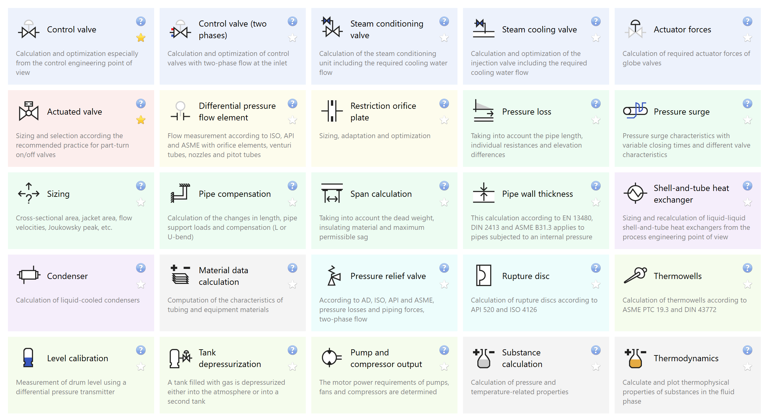
Figure 1
All these modules are subject to constant further development and maintenance, based on the development of standards, the latest findings from research and development or simply driven by user requirements, so that the software is updated several times a year. Proposals for standard adaptations, such as improvements to DIN/IEC 60534-2-1 for viscosity correction presented here, *1can be made available to users immediately.
In addition, new main versions are released cyclically, as was just the case with Release 11, which, in addition to extensive improvements and expansion of existing functionality, also contains completely new modules.
Standards maintenance has taken place in the safety valve module, here the calculation of two-phase flows according to the current ISO 4126-10 has been added, previously only the Omega method of API 520 was available. Another example of extensions to existing modules is the calculation of boundary hole discs. Long integrated in the control valve module for multi-stage relief on the downstream side of the valve, it now also offers multi-stage design of single or multi-hole discs in the detached variant.
A current case from practice enables a customer (a Valve Integration Center in the USA) to quickly and flexibly design multi-stage single-hole discs that are connected in front of the valve in steam applications.
Whereas in the past it took hours for an initial design, with CONVAL® the design can be done in minutes, and a recalculation with changed operating data can even be done with just a few clicks in the programme. CONVAL® already suggests sensible differential pressures during the design, determines and takes into account the necessary plate thicknesses, etc., i.e. it not only performs the calculation, but also suggests a design that has been tried and tested from experience and can then be modified. Or, as in this case, a customer's design (Figure 2), which was too loud, could be improved considerably (the overall sound level was reduced by 5dB(A)) by using the design automation in CONVAL®
(Figure 3).
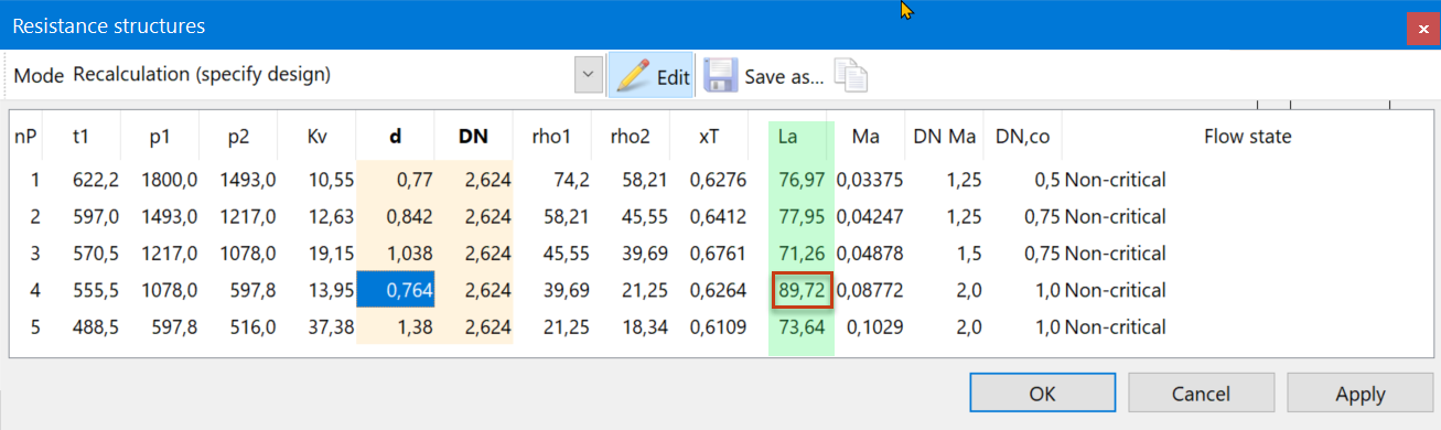
Figure 2
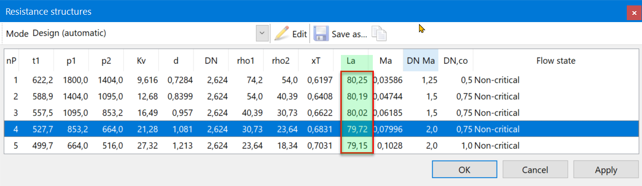
Figure 3
New modules enable, for example, the calculation of control valves for steam coolers or the design of the drive train of automated valve assemblies with quarter-turn actuators.
The latter is based on the "Recommended Practice S2812-X-19" (hereinafter referred to as RP) published by the WIB*2 in June 2019. We have already published a basic article on this topic in Industrial Valves*3 and Industrial Fittings*4.
In addition to the technical implementation, which must be able to capture and calculate all eventualities of an application, CONVAL® focuses on the presentation and visualisation of the results. Users who do not work on valve topics on a daily basis find it difficult to interpret the results.
In order to ensure that the resulting evaluation is reproducable - regardless of the person - the software has a long history of using KPIs*5 and a traffic light system for the evaluation, as well as graphical representations to clearly illustrate the facts. In the area of control valves*6 , this has long been a standard feature of CONVAL® and has also been consistently implemented in new modules, e.g., for automated valve assemblies (Figure 2). Whereas control valves have a reliability and controllability index, here there is a suitability index (SI), which clearly indicates how well a selected actuator fits the valve application. As with the other KPIs in CONVAL®, the rule is: the closer to 0 the better.
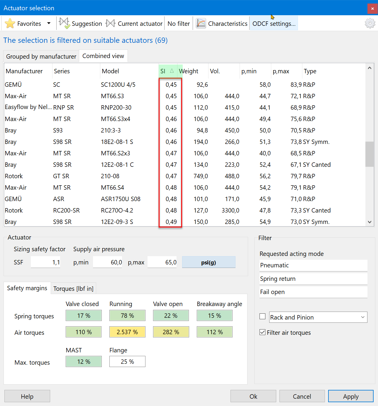
Figure 4
In addition, a traffic light system (Figure 5) quickly indicates the suitability of the selection for the application. The graphical presentation of the underlying data complements and explains the evaluation of the traffic light system.
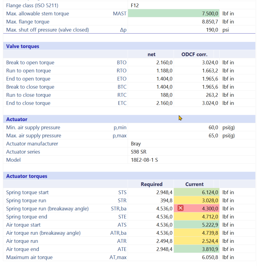
Figure 5
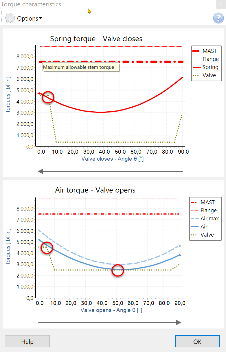
Figure 6
The examples given make it clear that CONVAL® is a solution that offers general, yet very detailed solutions for all valve applications (and more). One essential point has not yet been mentioned, but it is what makes the whole application complete, and that is the device data and properties. In our view, it is by far the most time-consuming part of software maintenance. In comparison, the implementation of the mathematics is easy.
With each new module we face the same challenges, namely to persuade and convince the manufacturers to make the data of their valves and actuators available. Whereas in the case of control valves we have succeeded step by step over the past decades in incorporating essential device data into CONVAL® in cooperation with the manufacturers and keeping it up to date, we are still at the beginning with quarter-turn valves and their actuators. But as is so often the case, the demand from our users worldwide plays its part when they approach the manufacturers and request the data in CONVAL® not only from us.
As a software manufacturer, we are not only looking to partner with end users here, but also with equipment suppliers, as we are convinced that together we can create an advantage for our mutual customers.
Well-documented exchange file formats in Excel and maintenance programmes are available for recording the data. It goes without saying that our support team assists the manufacturers with advice, practical assistance and test licences to ensure quality assurance.
*1. Vulkan Verlag - Industrial valves, Issue 4/2020 Improvements in the Kv value calculation of control valves with small valve Reynolds numbers
*2. WIB - "The International Process Automation Users' Association" www.WIB.nl
*3. Vulkan Verlag - Industrial Valves, Heft 2018/2019, "How to solve the Actuated Valve (AV) Assembly Torque Requirement Puzzle? ”
*4. Vulkan Verlag - Industriearmaturen, Issue 3/2020The treatment of "Automated Valve Assemblies" as "Engineered Products".
*5. Key Performance Indicator - Evaluation ratios for calculation results
*6. Vulkan Verlag - Industrial valves, issue 2/2012 Performance analysis of valves using a reliability index in CONVAL®
If you require further information on this product or would like a quotation, please contact dp-flow on:
email: sales@dp-flow.co.uk
sales +44(0)1608 544222
Treating of "Automated Valve Assemblies" as "Engineered Products"
What does the implementation of Recommended Practice S2812-X-19 or ISO/TC 153 N 425, ISO/NP 5115 in practice mean for the various groups involved such as valve and actuator manufacturers, integrators, and end-users of automated valve assemblies?
ANDREAS VOGT F.I.R.S.T. GESELLSCHAFT FÜR TECHNISCH-WISSENSCHAFTLICHE SOFTWAREANWENDUNGEN MBH
In June 2019, the "Recommended Practice S2812-X-19" (hereinafter referred to as RP) was published by the WIB at the Valve World Americas Conference in Houston. The RP is entitled "Actuated Valve Assembly - A Recommended Practice for Part turn Automated On-Off valves" and addresses the issue (including the definition of the general conditions) of sizing, selection, and the mechanical integrity of automated valve assemblies widely used in many industries.
Since F.I.R.S.T. has comprehensively supported the development of the RP both in principle and with functional prototypes, it is a matter of course that a module will soon be available in CONVAL® that fully maps the RP. Recognizing the importance of the issue for the worldwide community, the ISO has taken up the task of developing an international ISO standard with RP as a basis. At this point, the ISO even goes one step further than the RP in considering electric actuators, as the RP is limited to pneumatic (and in a broader context hydraulic) actuators.
I have already published a paper on this topic in Industrial Valves , so I will not go into all the details of the RP here but only give an overview. The focus will be on the requirements for the implementation of the RP in practice, from the various perspectives. The viewpoint of the manufacturers of the valves, the actuators, possible integrators as well as that of the end-users.
Recently I gave two webinars on this topic at the virtual "Forum Industriearmaturen" and during the introduction, I made a small poll among the participants. Each one of the webinar participants confirmed that they had cases of valves in their practice that did not open or close when required or even sheared off the stem. For me a clear indication of the importance of the topic for the industrial valve user community.
If one were to summarise the objectives of the RPs in a few sentences, it could be described as follows:
If you automate rotary valves as shut-off valves, you have to find the right actuator for the required torque, which is derived from the valve and application data.
- On the one hand, this actuator should have enough torque and an adequate safety margin to operate the valve safely under all expected conditions
- On the other hand, it should not be oversized, and not just for cost reasons. It must not be designed in such a way that the torque delivered may damage the valve, seat, or stem
- The design should take into account all relevant data and conditions of the equipment used and the application itself
- The selection made should be documented comprehensively, completely, and uniformly so that it can be traced at any time
When you look at the RP it quickly becomes clear that the approach described makes perfect sense by itself, but immediately raises many more questions and demands on the groups involved. I have already outlined these in the DIAM 2019 lecture program. It should not be forgotten that RP was initially conceived from the perspective and driven by the needs of end-users in the process industry. However, to implement it, a profound acceptance, transparency, and openness on the part of the manufacturers of actuators and especially valves are required.
But first to the question "Why all this?”. In short, because today automated valves are not treated as "Engineered Product". Safety, application, and possible further factors remain unclear and the procurement of valve, coupling, and the actuator is often in different hands. As a result, they are not considered as assemblies and responsibilities for the final delivered solution often remain unclear.
The RP clearly defines the responsibilities for the required data and keeps them in the documentation, the "Automated Valve Data Sheet". There (extract in Figure 1), the right-hand column clearly shows who is responsible for the data.
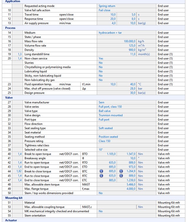
Figure 1
Nothing is surprising on the end-user side, the data can all be obtained from the process engineering department and the valve manufacturer. However, if you want to choose a suitable actuator, you will need a lot more information about the valve, the mounting kit, and the potential actuator.
Ideally, as implemented in CONVAL®, the requirements of the process are specified, supplemented by information on factors (media properties, long standstill times, etc.) that could further influence the torque requirement, a valve is selected from the database and, after entering a safety factor for the design, the appropriate actuator can be selected.
This ideal case, however, requires that valve and actuator manufacturers have determined and published the required key parameters of their devices and that these are also stored in the database. Of course, manual input is always possible if the data is not available in the database.
On the actuator side, this is standard, usually the data on torques, flange design according to ISO 5211 , etc. are published in full. Even if these have not yet been captured in the database, the entry is quickly completed with just a few values, taken directly from the documentation of the actuator manufacturer.
With the valves, the situation is different for a variety of reasons. Things like the MAST (Maximum Allowable Stem Torque) can still be found, depending on the stem material (example Figure 2), as they are more or less easy to calculate by the manufacturer. The flange class according to ISO 5211 is also no problem. However, RP still expects, for the calculation of the required torque of the valve, six different torques (as shown in Figure 3 as an example) matching the differential pressure. Furthermore, a breakaway angle as well as correction factors for the application are required.
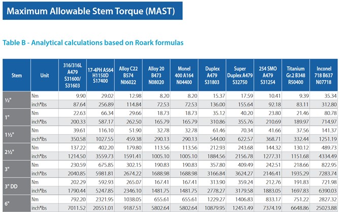
Figure 2
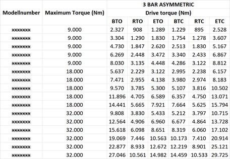
Figure 3
Sometimes, however, the maximum torque is the only information available. There are rules of thumb (for each valve style) like e.g. BTO, ETC = 100%, RTO, RTC=40%-50%, ETO, BTC=70%, but these should be used with caution and do not conform to the RP or the upcoming ISO standard.
In practice, however, there are unfortunately hardly any publicly available and fully documented torques, so that there seems to be a considerable backlog demand on the part of the valve manufacturers.
The situation is similar for the correction factors for the application conditions (defined as ODCFs in the RP). Some manufacturers specify factors for different situations (example Figure 4), but these do not necessarily correspond to the system of factors in the ODCFs and certainly do not define how to proceed when several factors come together (add, increase, multiply, etc.).
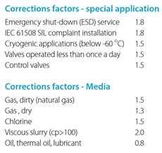
Figure 4
As defined by the RP, CONVAL® allows each manufacturer of valves to configure these factors for each valve series and to define how they are handled individually. This applies to the factors and their application limits (see Figure 5) as well as to the question to which torque the factor should be applied (see Figure 6). For example, by default (RP recommendation) the factor for long standstill times for the safety function "spring closes" is only applied to the BTC, for "spring opens" only to the BTO.
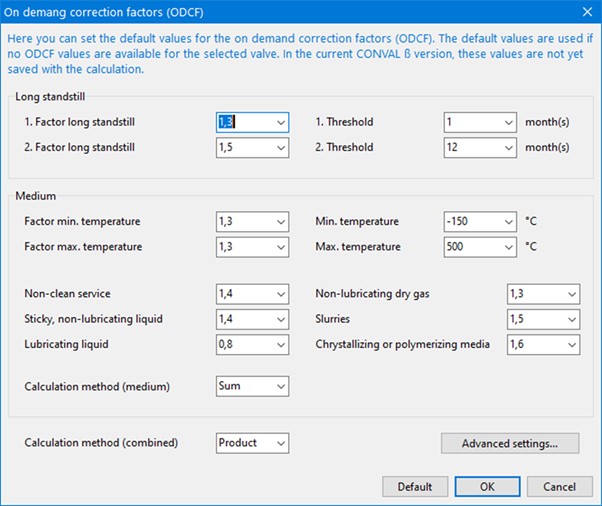
Figure 5
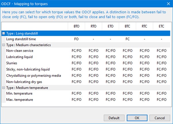
Figure 6
In the case of series-production valves (larger number of pieces/year), there is a chance to obtain this data from the manufacturer, but in the case of so-called "one of a kind", i.e. unique valves specially designed for the case, the effort and cost to determine the data are enormously high. In this case, the user can only make progress through intensive cooperation with the manufacturer.
The described situation makes it very clear how detailed the determination of the required torques for the safe operation of the valve is implemented in the RP and will soon be required by ISO. It is obvious which hurdles still have to be overcome before an end-user, or whoever has to find the right actuator for a valve, can simply follow the RP and comply with the ISO.
But once the hurdles have been overcome and the necessary data made available, these can, in combination with a software module such as in CONVAL®, make design, selection, and documentation considerably easier, more reliable, and reproducible.
If all the data is available, a suitable actuator, automatically rated and sorted by a "Suitability Index" (KPI for the suitability of the actuator for the application) is suggested and the selection is clearly structured (Figure 7) and graphically supported (Figure 8).
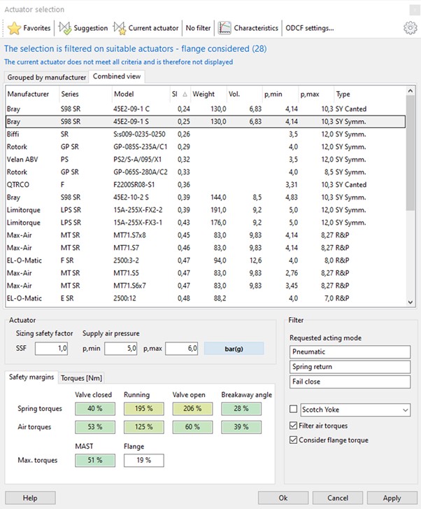
Figure 7
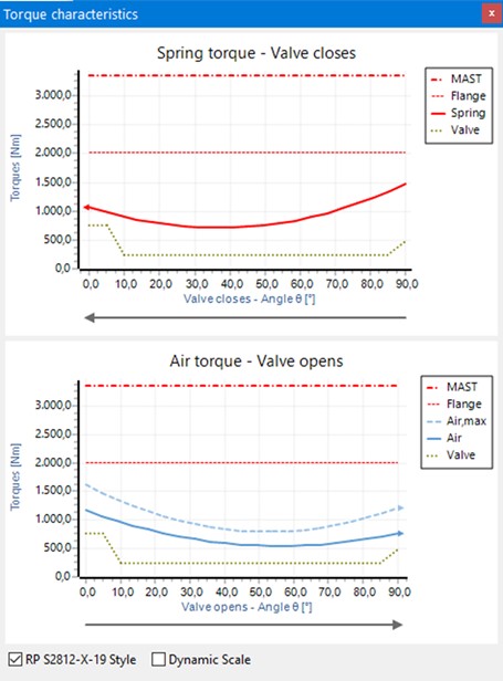
Figure 8
It is clear that the path is well described and tools for implementation will soon be available. However, based on decades of practical experience in the field of control valves, I assume that it will still take considerable time and effort until device data is generally available and of good quality but that should not prevent us from embarking on this approach now.
If you require further information on this product or would like a quotation, please contact dp-flow on:
email: sales@dp-flow.co.uk
sales +44(0)1608 544222
Nuclear Industry- ELECTROMAGNETIC FLOWMETER
[[background]]{{/if"}"}
[[the-problem]]{{/if"}"}
[[the-solution]]{{/if"}"}
[[further-information]]{{/if"}"}
[[equipment-description]]{{/if"}"}
British Energy - Caemes Bay - Minisonic 600 / 2000
[[background]]{{/if"}"}
[[the-problem]]{{/if"}"}
[[the-solution]]{{/if"}"}
[[further-information]]{{/if"}"}
[[equipment-description]]{{/if"}"}
BT Data Centre Bletchley - Minisonic Clamp On
[[background]]{{/if"}"}
[[the-problem]]{{/if"}"}
[[the-solution]]{{/if"}"}
[[further-information]]{{/if"}"}
[[equipment-description]]{{/if"}"}
Flexsys Rubber Chemicals - MINISONIC CLAMP ON
[[background]]{{/if"}"}
[[the-problem]]{{/if"}"}
[[the-solution]]{{/if"}"}
[[further-information]]{{/if"}"}
[[equipment-description]]{{/if"}"}
Airbus A380 Minisonic Clamp On
[[background]]{{/if"}"}
[[the-problem]]{{/if"}"}
[[the-solution]]{{/if"}"}
[[further-information]]{{/if"}"}
[[equipment-description]]{{/if"}"}
Cardiff Bay Wetlands Project - Minisonic 600
[[background]]{{/if"}"}
[[the-problem]]{{/if"}"}
[[the-solution]]{{/if"}"}
[[further-information]]{{/if"}"}
[[equipment-description]]{{/if"}"}
Tilmanstone Salads
[[background]]{{/if"}"}
[[the-problem]]{{/if"}"}
[[the-solution]]{{/if"}"}
[[further-information]]{{/if"}"}
[[equipment-description]]{{/if"}"}
Corona Virus -19 CONVAL Network Extension by F.I.R.S.T.
[[background]]{{/if"}"}
[[the-problem]]{{/if"}"}
[[the-solution]]{{/if"}"}
[[further-information]]{{/if"}"}
[[equipment-description]]{{/if"}"}
[[relatedarticles]]{{/if"}"}
Hot Syn Gas Flows
[[background]]{{/if"}"}
[[the-problem]]{{/if"}"}
[[the-solution]]{{/if"}"}
[[further-information]]{{/if"}"}
[[equipment-description]]{{/if"}"}
[[relatedarticles]]{{/if"}"}
MRK Orifice and Carrier for Calcinator Process
[[background]]{{/if"}"}
[[the-problem]]{{/if"}"}
[[the-solution]]{{/if"}"}
[[further-information]]{{/if"}"}
[[equipment-description]]{{/if"}"}
[[relatedarticles]]{{/if"}"}