Multi Stage Single Hole Pressure Reduction for Liquids and Gasses SDP-L SDP-G
Manufactured by ![]()
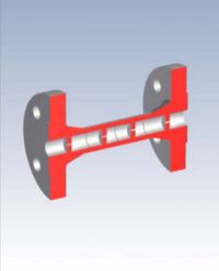
Single Hole/Multi Stage Pressure Reducing Unit For Liquids type SDP-L
The EMCO single hole multi stage pressure reducing units are used to prevent critical/high pressure drops in continuous liquid flow pipe lines. By reducing the pressure in stages the damaging cavitation is avoided. This secures long life time of the equipment. The calculation is based on ISO 5167, and on a critical flow factor or cavitation factor for determining allowed pressure loss across each stage. Each of the pressure reducing stages are connected and supplied as a unit. Main applications include boiler feed water by-pass lines. Boiler feed water pump circulation and warm up systems, boiler drum blow down.
EMCO Single Hole/Multi Stage Depressurizing Unit for Gasses type SDP-G
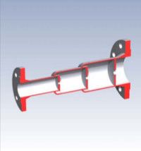
The EMCO Single Hole/Multi Stage Depressurizing Unit for Gasses type SDP-G are used to reduce the pressure in a number of stages to a desired pressure. The gas passes each stage at sonic or critical velocity. When the pressure is reduced so is the density of the gas or steam. In order to maintain a constant velocity the cross sectional area is increased after each stage The calculation is based on R.W. Miller and Ward-Smith. Each of the pressure reducing stages are connected and supplied as a unit.
EMCO Single hole/Multi stage Pressure Reducing Unit for Liquid Type SDP-L
EMCO single hole multi stage pressure reducing units are used to prevent critical/high pressure drops in continuous liquid flow pipe lines.
By reducing the pressure in stages the damaging cavitation is avoided. This secures long life time of the equipment. Cavitation occurs during pressure reduction when the pressure in the Vena Contracta (the bore of the plate) is lower than the vapour pressure. Cavitation generates noise, erosion and vibrations.
The calculation is based on ISO 5167, and a critical flow factor or cavitation factor for determining allowed pressure loss across each stage. Each of the pressure reducing stages are connected and supplied as a unit.
Main applications
Boiler feed water by-pass lines. Boiler feed water pump circulation and warm up systems. Boiler drum blow down.
Design and calculation standards :
- ISO 5167, Handbook, R.W. Miller: Flow Measurement Engineering Handbook, etc., ASME
- Sizes : DN 15 – 150, 1/2" - 6", larger sizes on request.
- Pressure rating : PN 16 – 400, 150 - 2500 lbs
- Multi stage design : Constant cavitation factor.
- Orifice plate shape : Square edge concentric.
- Thickness calculation : ASME standard.
- Plate thickness : Minimum 3 mm, thickness is calculated to handle the differential pressure.
- Distance between each stage: 2- 3 times inner pipe diameter.
- Discharge coefficient : ca. 0,6
- Material, plates : AISI 316 (standard), and other erosion resistance materials like 13CrMo4-5 (F11), 10CrMo9-10 (F22)
- Material, spool piece : P235GH (A106 Gr. B or C), 16Mo3 (F1), other materials on request.
- Mounting style : Between flanges according to ANSI B16.5 or DIN Standards or butt or socket weld ends.
- Overall length : Depends on number of stages and pipesize. Each SDP-L is calculated individually.
- Documentation : Material certificate according to EN 10204-3.1.
If you require further information on this product or would like a quotation, please contact dp-flow on:
email: sales@dp-flow.co.uk
sales +44(0)1608 544222
Supplied by DP-Flow