PITOBAR
DK200; ;DK201; ;DK202; ;DN203; ;DK204;
DK250; ;DK251; ;DK252; ;DK253; ;DK254
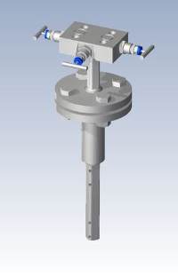
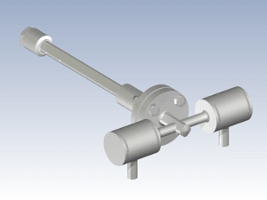
The EMCO PITOBAR Averaging Pitot Tube is used for flow measurement of liquids gases and steam in circular or rectangular pipes or ducts.
Pitotbars are installed in power stations, petrochemical and chemical plants, pollution control applications, water treatment plant, refineries and steel plants. Averaging pitot tubes can be inserted in to pipelines under pressure (hot tap and retractable under pressure) to measure a wide range of fluids. These range from super heated steam, saturated steam, boiler feed water, bio gas (biogas), Syngas, dirty gas flows, stack gas for emissions monitoring and others. We can supply purge systems including constant positive air supply purge pressure systems to ensure particulates do not enter the impact / dynamic pressure ports of the pitot. The port holes have different sizes depending on the model, for gases liable to condensation, large pressure ports are required to prevent water column forming in the impulse lines and pressure channels.
The PITOBAR Averaging Pitot tube principle of operation is derived from the classic or single point pitot tube, which has been used in industry for many decades.
The single point pitot tube is manually moved up and down the pipe or duct to measure the flow (dynamic pressure). The PITOBAR averaging pitot tube has a number of holes depending on the pipe size pointing towards the upstream side. Generally one port points downstream to measure the static pressure, however where we require bi directional measurement, we ensure the upstream and downstream ports are replicated on both sides of the sensor, providing full bi-directionality. The transmitters can be ranged accordingly (-100% to +100% = 4=20mA, 12 mA=0 flow) or we can stack transmitters with the +/- sides of the transmitters reversed to give full rangability. For wide flow ranges we have our multi range transmitters offering 400:1 turndown, reducing the number of transmitters required.
The fluid must be single phase and the pipe must be full in the measurement section. Changes in flow rate must be slow and non pulsing.
The PITOBAR has a low installation cost, and the pressure loss is low compared to other flow elements, especially in large pipe sizes.
Construction and Design
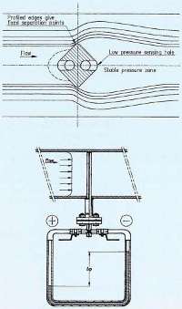
The PITOBAR Averaging Pitot Tube is constructed and designed with a diamond shaped profile and several ports spaced centrally within concentric rings of equal area pointing upstream. This is done in order to get the best averaging measurement of the dynamic pressure, resulting in a more accurate flow reading.
The pitot tube creates a differential pressure signal which is proportional to the flow rate in accordance with Bernoullis' law.

Differential pressure = (Pstatic+Pdynamic)-Pstatic
There is a square root relationship between flow and differential pressure.
Pd= dynamic pressure, rho = density, k=constant, A=area, Q=flow
Technical Specifications
- Sizes : DN50-DN8000, 2"-320"
- Pressure Rating:PN16-400, 150-2500 lbs, ISO PN20, 50, 100, 150, 250, 420
- Temperature range : -100 to +900 C
- Materials - Stainless Steel, CrMo Steel, Hastelloy C, Inconel, Monel, titanium, PVDF, Others on request.
- Process connections: Flange according to pressure rating, all welded construction
- Flange Standards: DIN, ANSI, ISO, others on request
- Mounting: Welded to pipe
- Accuracy : 1% of flow
- repeatability : 0.1%
- Range : 10:1
- Max dp :dependent on type, size and fluid (density and velocity)
- Max fluid Velocity: see "frequency calculation"
- Probe sizes : DK20*: 20x20 mm; DK*25: 25x25 mm; PC*45, PC55*: 45x45 mm
- Special applications: Purge connections, all welded versions for high pressure/ temperature steam flow
- * indicates the type, e.g.DK202
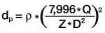
Differential Pressure Calculation
The differential pressure is calculated using the equations listed below. Contact us for an official calculation
- Liquid (Volumetric flow m3/h)
- Gas (Volumetric flow Nm3/h)
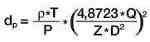
- Liquid, Gas and Steam (Mass flow kg/h)
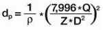
- dp=differential pressure in KPa
- rho=density kg/m3 or kg/Nm3
- t=absolute temperature in K
- P=absolute pressure in KPa
- Q=flow rate in Nm3/h, m3/k, kg/h
- D=internal pipe diameter mm
- Z=flow factor (sensor specific)
Range / Turndown
The turn down range of the PITOBAR is determined by the limits of the minimum and maximum flow where the flow factor is constant within a range of Reynolds numbers.
The flow must be turbulent which means a Reynolds number above 10,000.
The best results are obtained if Reynolds is above 100,000.
- Re=(V*D)/nu
- V=Velocity, D = Pipe ID, nu = kinematic viscosity
Construction
The range of the PITOBAR averaging pitot tube is defined as a maximum flow over a minimum flow for a given accuracy.
With one differential pressure transmitter of the smart type the range is at least 10:1 within the given limits for a Reynolds number with a reasonable accuracy.
the PITOBAR has a diamond shape which gives a defined separation point.
The separation point secures a stable pressure zone around the static pressure hole, ensuring correct static pressure measurement.
Derived from the equation for the differential pressure calculation it is important to measure the static pressure correctly, in order to measure the true differential pressure. therefore, the flow around the profile is of vital importance to the range and accuracy.
Maximum allowable differential pressure
The maximum allowable differential pressure is an indication of which type of PITOBAR to choose to avoid bends or cracks. Due to the mechanical stress factors the maximum allowable dp should be taken in to consideration. If the actual differential pressure exceeds the maximum allowable it is advisable to choose another flow sensor.
Maximum allowable differential pressure in bar, without bottom support, with reference to mechanical bend.
The critical flow velocity should also be taken in to consideration, see section below.
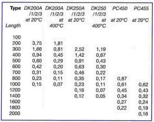
Frequency calculation
A frequency check is not necessary for liquid flows since the maximum allowable differential pressure is reached before the limit, due to its own frequency.
However, it is necessary to check the frequency limit for gas and steam flows. If the PITOBAR tube is used in a zone where the STROUHOL frequency and the natural frequency of the pitot tube coincide, the tube may oscillate to failure.
The critical flow velocity must therefore be considered. The critical flow velocity is dependent on the length of the probe equal to the internal pipe diameter.
Velocities between 1st and 2nd order frequency vibrations +/- 105 are not critical. Only if the flow velocity coincides with the critical flow velocity for a longer period, there exists a risk of natural oscillation to failure.
The critical flow velocity is inversely proportional to the square root of the length.
To check, either contact us or use the equation below.
If in doubt, use an opposite support.
Without bottom support:
Type DK200/1/2/3-A, 1st order frequency. ![]()
type DK250/1/2/3-A, 1st order frequency.![]()
With bottom support:
type DK200/1/2/3-A, 1st order frequency. ![]()
type DK250/1/2/3-A, 1st order frequency.![]()
D= pipe i/d in meters, v=velocity in m/s
Pressure loss
The pressure loss varies from 10% of the measured differential pressure in the smaller pipe sizes to less than 2% in large sizes.
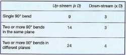
Installation requirements
Certain installation requirements for straight pipe must be fulfilled in order to achieve the most accurate flow measurement.
Required straight lengths
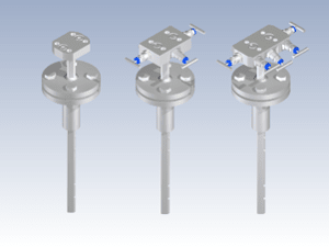
PITOBAR Types
DK200, DK250
Standard types for liquid and gas flow measurement
Sizes
DK200: DN50-1000, 2"-40"
DK250: DN100-2000, 4"-80"
Pressure rating up to PN400, 2500 lbs
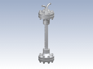
DK201, DK251
Flow sensors including condensation pots for steam flow measurement
Sizes
DK201: DN50-1000, 2"-40"
DK251: DN100-2000, 4"-80"
Pressure rating up to PN160, 900 lbs
DK202, DK252
retractable pitots for processes under pressure
Sizes
DN100-1500, 4"-60"
Pressure rating up to PN100, 600 lbs
DK203, DK253
As for DK200/250, but with mounting flange for direct mount transmitters
Sizes
DK203: DN50-1000, 2"-40"
DK253: DN100-2000, 4"-80"
Pressure rating up to PN400, 2500 lbs
PC 450, 455, 550, 555
Type 450, 455: flow sensors in heavy duty design for gas and liquid flow measurement in larger pipe sizes.
Sizes
DN400-DN8000, 16"-320"
Pressure rating up to PN40, 300 lbs, higher on request
Type 550, 555: flow sensors made in PVDF for flow measurement of corrosive liquids and gases.
Sizes
DN400-DN2000, 16"-80"
Pressure rating up to PN16, 150 lbs, higher on request
DK261
flow sensor specially developed for steam at high pressure and temperature.
type DK261 is for pressure above 80 Bar. All welded construction and includes condensing chambers.
Sizes
DN100-500, 4"-20"
Temp Max 580 C
Pressure max 300 bar
Mounting Installations
Liquid
PITOBAR flow sensors are widely used for liquid flow measurement in horizontal or vertical pipe. In horizontal pipe the PITOBAR is to be mounted in the centre line or below. The differential pressure transmitter shall be mounted below the PITOBAR to let air escape back in to the main process. If the liquid is not clean the flow sensor can be purged through two purge connections as an option.
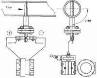
Gas
The PITOBAR flow sensor measures air of gases on round pipes or rectangular ducts in horizontal or vertical pipe runs. In horizontal pipes the PITOBAR is to be mounted in the centre line or above. The transmitter must be mounted above the PITOBAR to allow condensate to run back in to the main process.
Steam
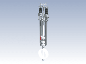
PITOBAR flow sensors for steam flow are supplied with condensing chambers for horizontal or vertical pipes.
The PITOBAR is mounted horizontally (on the side of the pipe). Preferably with a slope up to 5 degrees above the centre line allowing condensate in the sensor to flow back into the main line.
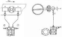
Retractable
PITOBAR flow sensors are available with retractable mechanism to withdraw the sensor from the process under pressure. the sensor can be cleaned or inspected before insertion into the process.
Purge connection
If the PITOBAR is used for a fluid with impurities it is advisable to supply purge connections on to the pitot. the PITOBAR can be purger continuously or periodically with a gas or a liquid compatible with the process fluid.
Secondary instrumentation
1. The simplest solution for flow reading is the differential pressure gauge, scaled in flowing units. This is only applicable for a local reading.
2. When remote indication or control is needed, a differential pressure transmitter is required. the flow related differential pressure is normally converted in to an electrical signal, 4-20mA. this signal is processed in a PLC, PID or flow computer depending on the application. It is possible to make a mass flow measurement with a PITOBAR for compressible fluids. the secondary instrumentation will then consist of the following equipment:
-differential pressure transmitter
-pressure transmitter
-temperature transmitter
-flow computer
However, many dp transmitters now include compensation for pressure and temperature which omits the necessity for a pressure transmitter. the temperature sensor is still required.
PITOBAR Coding
| PITOBAR Coding | |||
| DK200, DK204, DK250, DK254 |
PC450, PC455 | PC550. PC555 | |
| Bottom Support | |||
| A | Excl bottom support | Excl bottom support | Excl bottom support |
| B | With bottom support | With bottom support | With bottom support |
| Pitot Tube Material | |||
| 0 | Stainless Steel AISI 316 | Stainless Steel AISI 316 | PVDF |
| 1 | Hastelloy | ||
| 2 | Incoloy | ||
| 3 | 254 SMO | ||
| 4 | Heat Resistant Steel CrMo - 10CrMo44 |
||
| 5 | Heat Resistant Steel CrMo - 13CrMo44 |
||
| 9 | Other, Please Specify | ||
| Mounting Parts | |||
| 0 | Carbon Steel | Carbon Steel | PVDF |
| 1 | Stainless Steel AISI 316 |
Stainless Steel AISI 316 |
|
| 2 | Heat Resistant Steel 13CrMo44 |
||
| 3 | Heat Resistant Steel 10CrMo910 |
||
| 9 | Other Please specify | ||
| Flange and Size Rating | |||
| 10 | DN32 PN16 | DN80 PN16 | DN80 PN16 |
| 11 | 1 1/2" #150lb RF | 3" #150lb RF | 3" #150lb RF |
| 20 | DN32 PN40 | DN80 PN40 | |
| 21 | 1 1/2"#300lb RF | 3" #300lb RF | |
| 30 | DN40 PN100 | ||
| 31 | 1 1/2" #600lb RF | ||
| 32 | 1 1/2" #600lb RTJ | ||
| 40 | DN40 PN160 | ||
| 41 | 1 1/2" #900lb RF | ||
| 42 | 1 1/2" #900lb RTJ | ||
| 50 | DN40 PN250 | ||
| 51 | 1 1/2" #1500lb RF | ||
| 52 | 1 1/2" #1500lb RTJ | ||
| 60 | DN40 PN320 | ||
| 70 | DN25 PN400 | ||
| 71 | 1 1/2" #2500lb RF | ||
| 72 | 1 1/2" #2500ln RTJ | ||
| 90 | Other, Please specify | Other, Please specify | Other, Please specify |
| Instrument Connection | |||
| 10 | 1/2" BSP | 1/2" BSP | 1/2" BSP |
| 11 | 1/2" NPT | 1/2" NPT | 1/2" NPT |
| 12 | Weld End 21.3mm dia | ||
| 13 | Other, Please specify | Other, Please specify | Other, Please specify |
| Pipe Position | |||
| H | Horizontal pipe line | Horizontal pipe line | Horizontal pipe line |
| V | Vertical pipe line | Vertical pipe line | Vertical pipe line |
| Length of mounting parts | |||
| 130 | 130 mm standard | 130 mm standard | 130 mm standard |
| 150 | 150 mm | 150 mm | 150 mm |
| Special Application | |||
| S | 1/4" purge connection | 1/4" purge connection | 1/4" purge connection |
Works with:-
Differential pressure transmitters:-IDP10; IDP15; IDP25; IDP31; IDP50
And all our Absolute Pressure and Gauge Pressure transmitters, Temperature sensors and mass flow computers.
MultiVariable Transmitters :- IMV25, IMV30
If you require further information on this product or would like a quotation, please contact dp-flow on:
email: sales@dp-flow.co.uk
sales +44(0)1608 544222
Supplied by DP-Flow